


38(t) gear/sprocket test (full track video added).
 06-21-2013, 06:43 PM
#1

I did a quick test of the new motor/gearbox combo I plan to use on the Panda 38(t). I hooked in into the StuG to get an idea of the speed, I was afraid it would be too slow, but it looks good. This little combo has some nice torque, steel gears and the size is perfect. It's designed for robots, the voltage, etc is fine with the RX-18. The shaft is slotted, I cut a styrene tube to fit and shimmed with .005 stock until snug. It's all temporary.
Second part is the kit track links drilled out with metal rod for pins, again, just temporary.
[youtube]http://www.youtube.com/watch?v=_8SDuJmmsXw[/youtube]
I want to dive into this, but there's no way I can skip over the Pz IV sitting in a box for the last few weeks.
Second part is the kit track links drilled out with metal rod for pins, again, just temporary.
[youtube]http://www.youtube.com/watch?v=_8SDuJmmsXw[/youtube]
I want to dive into this, but there's no way I can skip over the Pz IV sitting in a box for the last few weeks.


 06-22-2013, 05:23 AM
#5
Educate me... where are these motors/gearboxes available from?
Looks like a good idea!
~ Jeff
Looks like a good idea!
~ Jeff
06-22-2013, 05:49 AM
#7
Thanks guys.
Jeff, it was Joe who gave me the heads up, here's the place:
www.robotmarketplace.com
They have a bunch of geared motors for robots, all different sizes, etc. I opted for these because the voltage range matched the Rx-18 and I could mount them in line, butt-ended and they'd fit in the hull. They're also thin enough that the sprocket position and outer glacis plate can remain intact.
They were $47 shipped for a pair (FLA to NY) and I had them in 2 days. Real steel gears, almost clock like in appearance and have a good amount of torque.
I can't promise any timely progress on this between the beginning of summer and the Tamiya Pz IV ahead of it, I just wanted to test things that arrived. The tracks alone are going to take at least a solid 10 (mindless) hours to drill out.
Suspension has to be addressed, I'll go the same route as I did with the T-34, brass sleeves, but I'll need to figure out the bogies. It's pretty similar to the Pz IV, but I don't think they'll need springs, just pivoting should be enough (besides there won't be much weight here.
I'll probably go Lipo, a 6 cell NiMH will just fit, but not much room for anything else. A 2 cell lipo will provide the same power in half the space.
06-22-2013, 05:53 AM
#8
Here's the exact motor:
http://www.robotmarketplace.com/prod...OPAL50-SH.html
Voltage:
4.8-14.8V
Output Speed:
300rpm @ 12V
150rpm @ 6V
Stall Torque:
58.9 oz-in (4241 g-cm) @ 12V
48.43 oz-in (3487 g-cm) @ 6V
Size:
1.46" (32.2 mm) long, 5/8" (16mm) diameter
Weight:
0.8oz (22.7g)
Gear Ratio:
Metal Spur gear 50:1
Stall Current:
Stall at 1.5a
Shaft Info:
4mm diameter with 2 flats; 9.5mm long
06-22-2013, 06:18 AM
#9
Any mounting prospects with the unit? Does/did it come with anything?
Thanks for your help as I do have an FT coming my way soon and I want to explore ALL ideas!
~ Jeff
Thanks for your help as I do have an FT coming my way soon and I want to explore ALL ideas!
~ Jeff
06-22-2013, 06:55 AM
#10
It didn't come with anything, but I think I got real lucky here. I test fit it into the kit and with the gear head flush with the hull side, the final drive cover in place, the sprockets fits perfectly in place, precisely the same as the kit pieces as intended.
I can't grab pics right now, but later this weekend.
I can't grab pics right now, but later this weekend.
06-22-2013, 08:30 AM
#12
Well, I'll wait for the kit FIRST... then see what kind of room I have and then go from there.
I like Eric Scott's build thread but want to put this project on a diet and save some room for the batteries. I can always add lead weight were it's needed.
~ Jeff
I like Eric Scott's build thread but want to put this project on a diet and save some room for the batteries. I can always add lead weight were it's needed.
~ Jeff
06-22-2013, 08:31 AM
#13
So you should be able to mount them by screwing them to the side of the hull?
06-22-2013, 08:47 AM
#14
I had forgotten about this site!!!! Thanks for sharing Joe!!! There are so many options in motors and gearboxes. Rex will think he has died and gone to Motor/Gearbox Heaven. Rex this site should have almost anything you need to bring some of your one of a kind creations to life!!![8D] Tortoise, Hint, Hint!!!
06-22-2013, 09:56 AM
#15
Senior Member

Another good resource for small motor gearboxes is at Pololu.com as well. They even sell 90 degree motor/gearbox combinations that may work for small tanks and vehicles.
Looking good ausf.
Dave
Looking good ausf.
Dave
06-22-2013, 12:22 PM
#16
ORIGINAL: MAUS45
So you should be able to mount them by screwing them to the side of the hull?
So you should be able to mount them by screwing them to the side of the hull?
06-22-2013, 05:03 PM
#17
Okay, some photos of the motor in the hull (just roughed out).
First up, I guess there is enough room for a NiMH.
The hull side is loosely in place but you can see the motor will fit. The front plate (inside of glacis) is the first of three pieces, so theres plenty of room to shave and add a holder of the motor itself if necessary. You can also see how two will fit across.

Second, a comparison of the original kit parts and how I cut to accomodate the gearbox.

Last, the alignment of the mounted motor/sprocket compared to the stock kit setup and the through mount itself which goes under the final drive cover.

There isn't much room in the gearhead itself for bolts, so I may 'clamp' the edges with bolts and washers, use Aves on both sides or a combo of both. The hull will absolutely need aluminum channel in the corner for support as well as cross-bracing.
Let me know if you have any ideas or see something or any comment at all. I'm just plowing through this, I may be missing something important I don't know about.
First up, I guess there is enough room for a NiMH.
The hull side is loosely in place but you can see the motor will fit. The front plate (inside of glacis) is the first of three pieces, so theres plenty of room to shave and add a holder of the motor itself if necessary. You can also see how two will fit across.
Second, a comparison of the original kit parts and how I cut to accomodate the gearbox.
Last, the alignment of the mounted motor/sprocket compared to the stock kit setup and the through mount itself which goes under the final drive cover.
There isn't much room in the gearhead itself for bolts, so I may 'clamp' the edges with bolts and washers, use Aves on both sides or a combo of both. The hull will absolutely need aluminum channel in the corner for support as well as cross-bracing.
Let me know if you have any ideas or see something or any comment at all. I'm just plowing through this, I may be missing something important I don't know about.
06-22-2013, 05:13 PM
#18

Join Date: May 2009
Location: Perth, ON, CANADA
Posts: 278
Likes: 0
Received 0 Likes
on
0 Posts
Talk about thinking outside the bun! Those robomotors are intriguing and the whole proto-build is looking excellent, Ausf.
If I were the designers at Tamiya, Henglong/Taigan/Mato/Matorro and the other various morphs of those companies, I'd be casting nervous looks over my shoulder. Could it be the RC community is tired of, and ready for something other than warmed over Shermans, early/mid/late/early-late-mid tigers and metal versions of each?
Bring on the 38Ts and FT-17s.
Mike.
06-22-2013, 05:44 PM
#19
Thanks Mike.
I don't want to get ahead of myself here, I don't know how this will work. The sprocket might shed teeth like a NHL defenseman or the links may spontaneously explode.
I still haven't looked at the turret ring, but at the slightest sign of trouble I'm running for the Hetzer plans.
I don't want to get ahead of myself here, I don't know how this will work. The sprocket might shed teeth like a NHL defenseman or the links may spontaneously explode.
I still haven't looked at the turret ring, but at the slightest sign of trouble I'm running for the Hetzer plans.
06-23-2013, 08:53 AM
#20
LOLOL!!!!!!!!!!!!
I have been looking at using these motores for some projects myself, this tank being one of them. I like what you are doing. My only concern with the mounting, which of course means nothing, is that being mounted directly to the outdrive plastic might cause stress cracks from the torque. I might have preferred using a mount like the one pictured on mine, and bolt it directly to a piece of aluminum in the lower hull or heavy styrene maybe? Just a thought, but I think the outdrive can be a weak point for a mount.
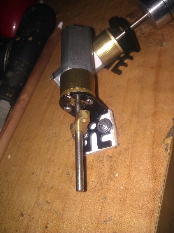
I have been looking at using these motores for some projects myself, this tank being one of them. I like what you are doing. My only concern with the mounting, which of course means nothing, is that being mounted directly to the outdrive plastic might cause stress cracks from the torque. I might have preferred using a mount like the one pictured on mine, and bolt it directly to a piece of aluminum in the lower hull or heavy styrene maybe? Just a thought, but I think the outdrive can be a weak point for a mount.
 06-23-2013, 08:58 AM
#21
Senior Member
I am very excited to see someone successfully rc one of the panda 38t kits. Defiantly keep us updated Ausf.
06-23-2013, 08:59 AM
#22

Those look great! Thanks for the video and all the info.
I purchased the 38(t) as a possible donor chassis for my Hetzer. If these gear boxes work I might be able to use them on both chassis!
Such a small gearbox should allow the room needed for the movement of the Hetzer's main gun. It also gets you much need space for the battery/speaker/electronics.
Good luck!
06-23-2013, 10:13 AM
#23
Thanks for the encouragement guys, I guess the IV is going to wait.
That's a good point about torque and styrene Joe. On my T-34, I bolted the TUs to eachother, the hull bottom and sides with metal reinforcement. This space is much tighter and the motor direction means all torque will be absorbed by the hull side. I can probably bolt the motors together and secure them to the aluminum hull reinforcement to start.
There's a good amount of space under the final drive cover, I can probably get a round brass plate that will positivelty lock the motor and bolt that to another on the inside (again cut out for the motor), essentially making a brass-styrene-brass Oreo. If I l bolt the inside piece to the hull alum angle, it'll be solid.
I just spent an hour reclining on the deck and managed to drill out 3 sprues of links with the pin vise (18 links total) So at 94 links per side, I guess I'll be out there for a while (960 holes). Luckily after 30+ years of playing bass, my right thumb and two first fingers are probably the strongest muscles in my body. Time to crack a Guinness or four and get to work. [8D]
That's a good point about torque and styrene Joe. On my T-34, I bolted the TUs to eachother, the hull bottom and sides with metal reinforcement. This space is much tighter and the motor direction means all torque will be absorbed by the hull side. I can probably bolt the motors together and secure them to the aluminum hull reinforcement to start.
There's a good amount of space under the final drive cover, I can probably get a round brass plate that will positivelty lock the motor and bolt that to another on the inside (again cut out for the motor), essentially making a brass-styrene-brass Oreo.
If I l bolt the inside piece to the hull alum angle, it'll be solid. I just spent an hour reclining on the deck and managed to drill out 3 sprues of links with the pin vise (18 links total) So at 94 links per side, I guess I'll be out there for a while (960 holes). Luckily after 30+ years of playing bass, my right thumb and two first fingers are probably the strongest muscles in my body. Time to crack a Guinness or four and get to work. [8D]
06-23-2013, 10:33 AM
#24
All this grrreat information needs to be followed up with casting some new sprockets and possibly a set of idlers too!
I know I'll be looking into it.
~ Jeff
I know I'll be looking into it.
~ Jeff

