


CK AERO Alchemy Pro Builder's Kit Foam Cores
 05-02-2022, 03:18 AM
#1

This will be my 1st crack at this. SHould be fun. Going to build a Alchemy Pro. Mostly posting this for two reasons:
1. I need help
2. For future reference and if anyone else wants to do this, they can use this as a guide.
When I purchased the kit, total was 1962.93 which was the Alchemy pro builders kit with the foam cores and the limited edition clear canopy.
Over the weekend, I was at the Houston Katy Pattern Contest, and I received the kit, and all i can say is "AMAZING".
the quality of the kit and the foam is top notch.
To me, seems like this will be quite straightofrward to get done.
I have a few questions and hopefully Bryan will be able to answer these here, when convenient for him.
Going to get started soon on this as well.
For servos, this is what I was thinking, but if anyone else has any suggestions, please chime in: Futaba BLS 171 for elevator and rudder. and the Futaba BLS 173 for the elevators
Now for some pictures:
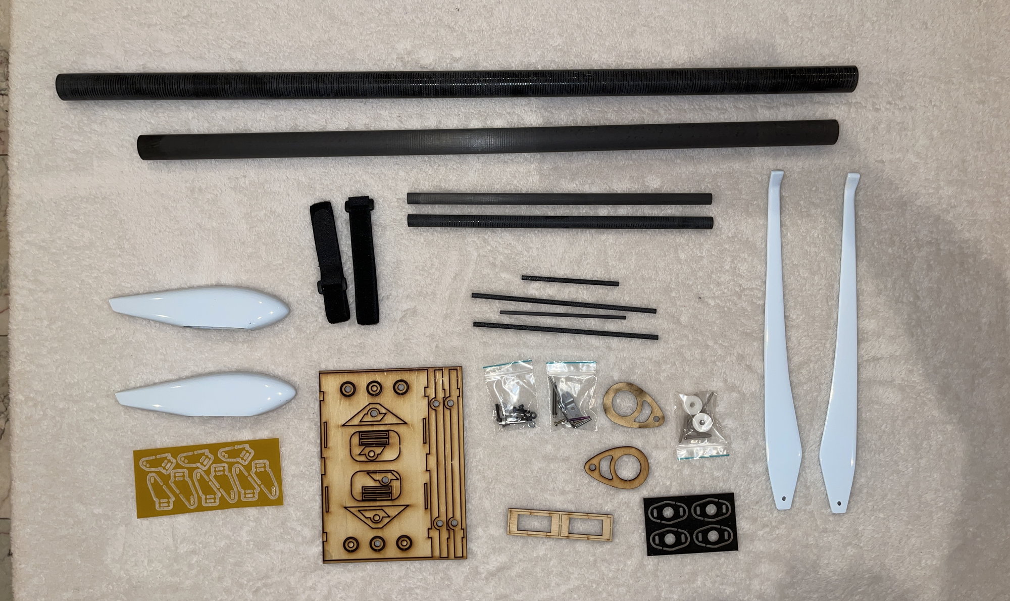
this was all nicely packed inside the Fuselage. Missing is the rudder, which was also inside the FUSE.
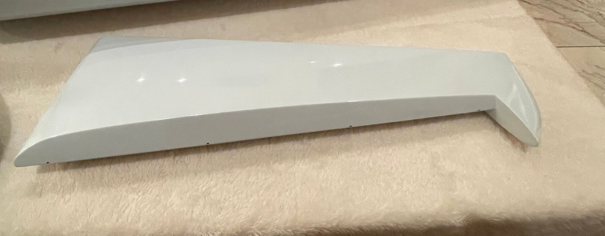
LE view of the rudder. Very high qualite and straight!
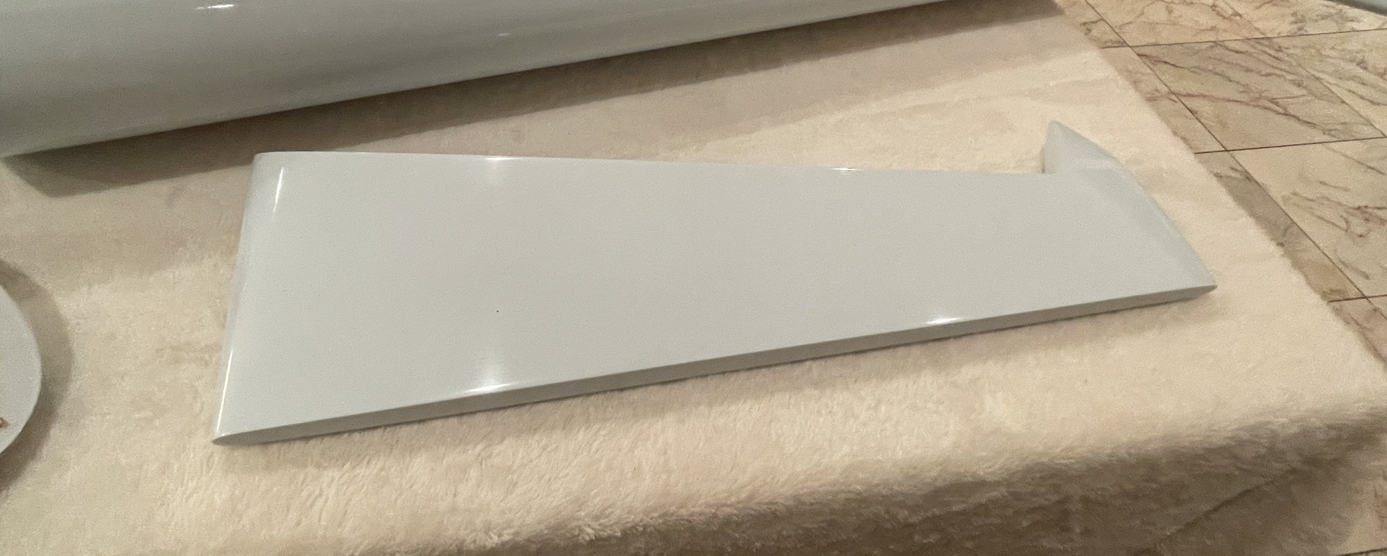
TE view of the rudder. THe Rudder was also packed inside the fuselage, covered with protective wrap foam.
1. I need help
2. For future reference and if anyone else wants to do this, they can use this as a guide.
When I purchased the kit, total was 1962.93 which was the Alchemy pro builders kit with the foam cores and the limited edition clear canopy.
Over the weekend, I was at the Houston Katy Pattern Contest, and I received the kit, and all i can say is "AMAZING".
the quality of the kit and the foam is top notch.
To me, seems like this will be quite straightofrward to get done.
I have a few questions and hopefully Bryan will be able to answer these here, when convenient for him.
Going to get started soon on this as well.
For servos, this is what I was thinking, but if anyone else has any suggestions, please chime in: Futaba BLS 171 for elevator and rudder. and the Futaba BLS 173 for the elevators
Now for some pictures:
this was all nicely packed inside the Fuselage. Missing is the rudder, which was also inside the FUSE.
LE view of the rudder. Very high qualite and straight!
TE view of the rudder. THe Rudder was also packed inside the fuselage, covered with protective wrap foam.
 05-02-2022, 03:27 AM
#2
This is where I will have some questions?
first, I was extremely & pleasantly surprised to remove the shuck from both the wing and stabs and see that the hinge line and servo box area was already marked out!! this makes it so much easier. Thank you so much Bryan!!
Some pictures and then the questions:
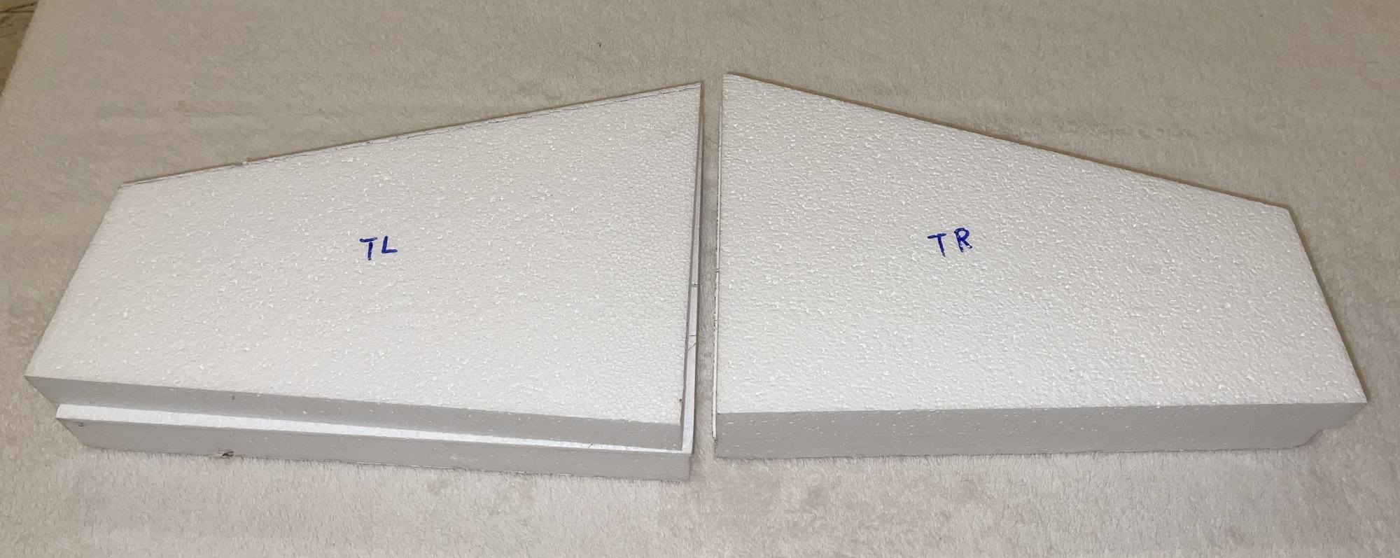
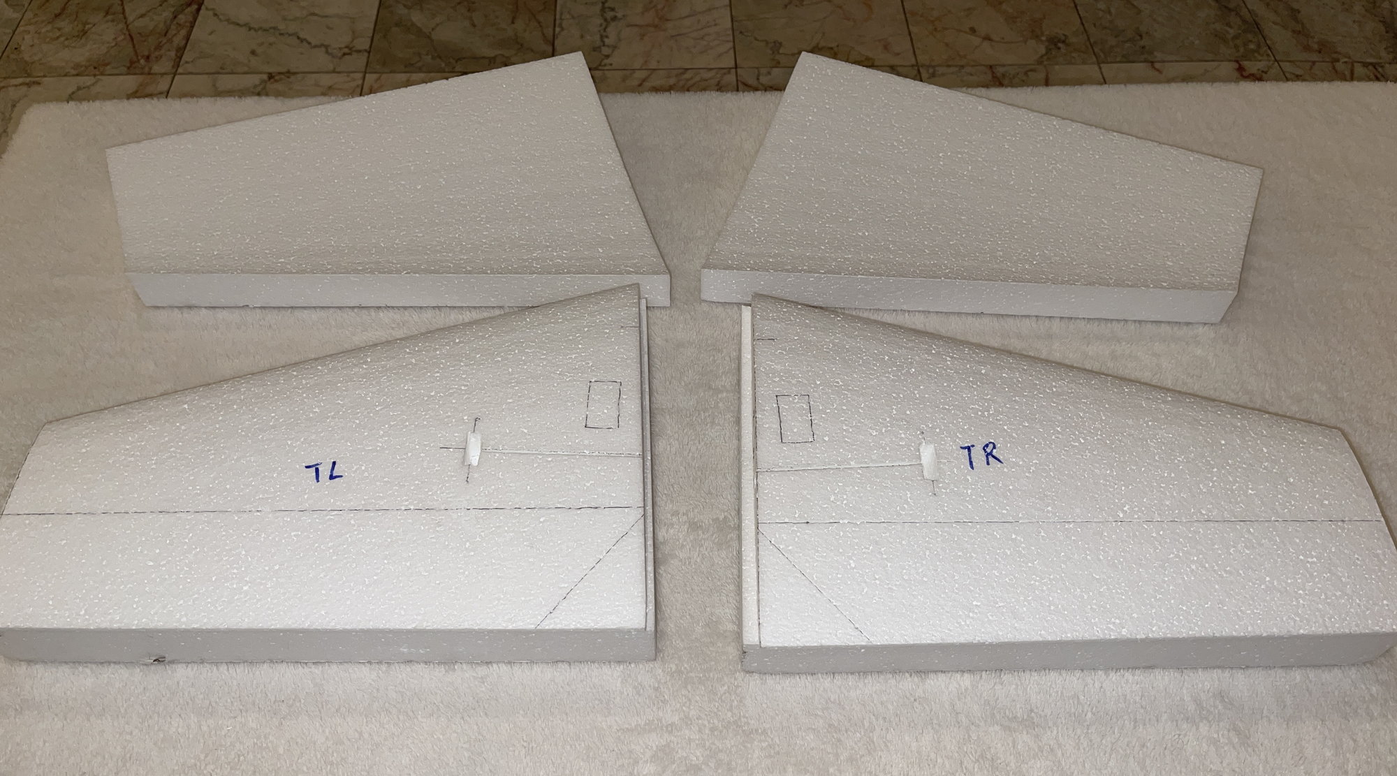
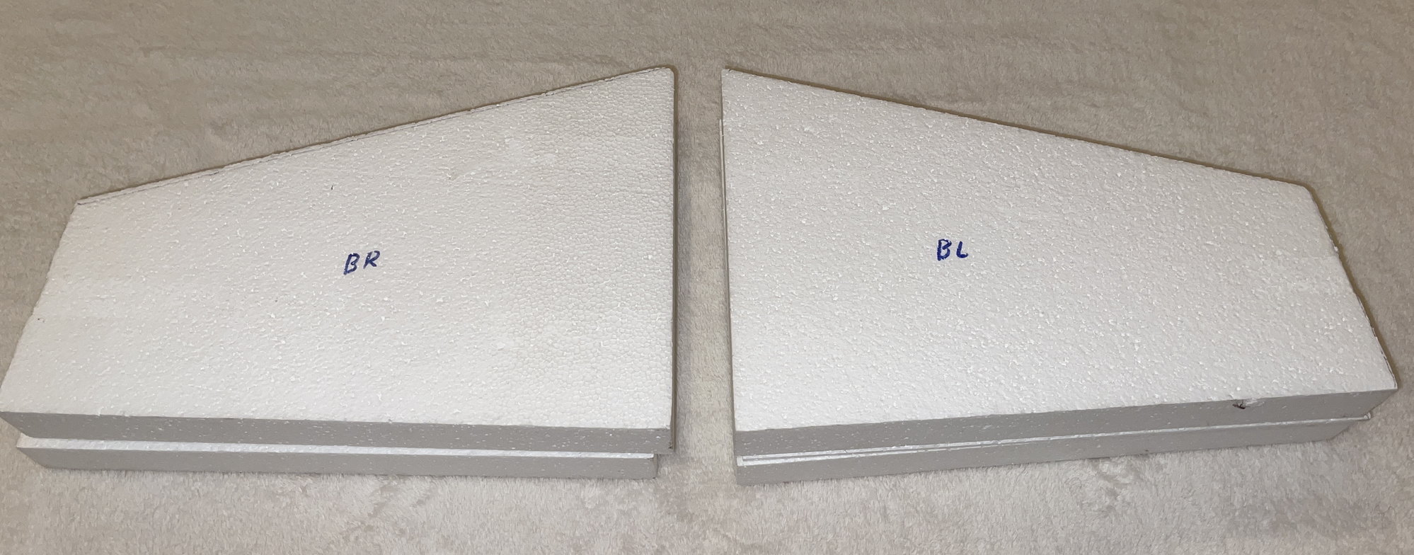
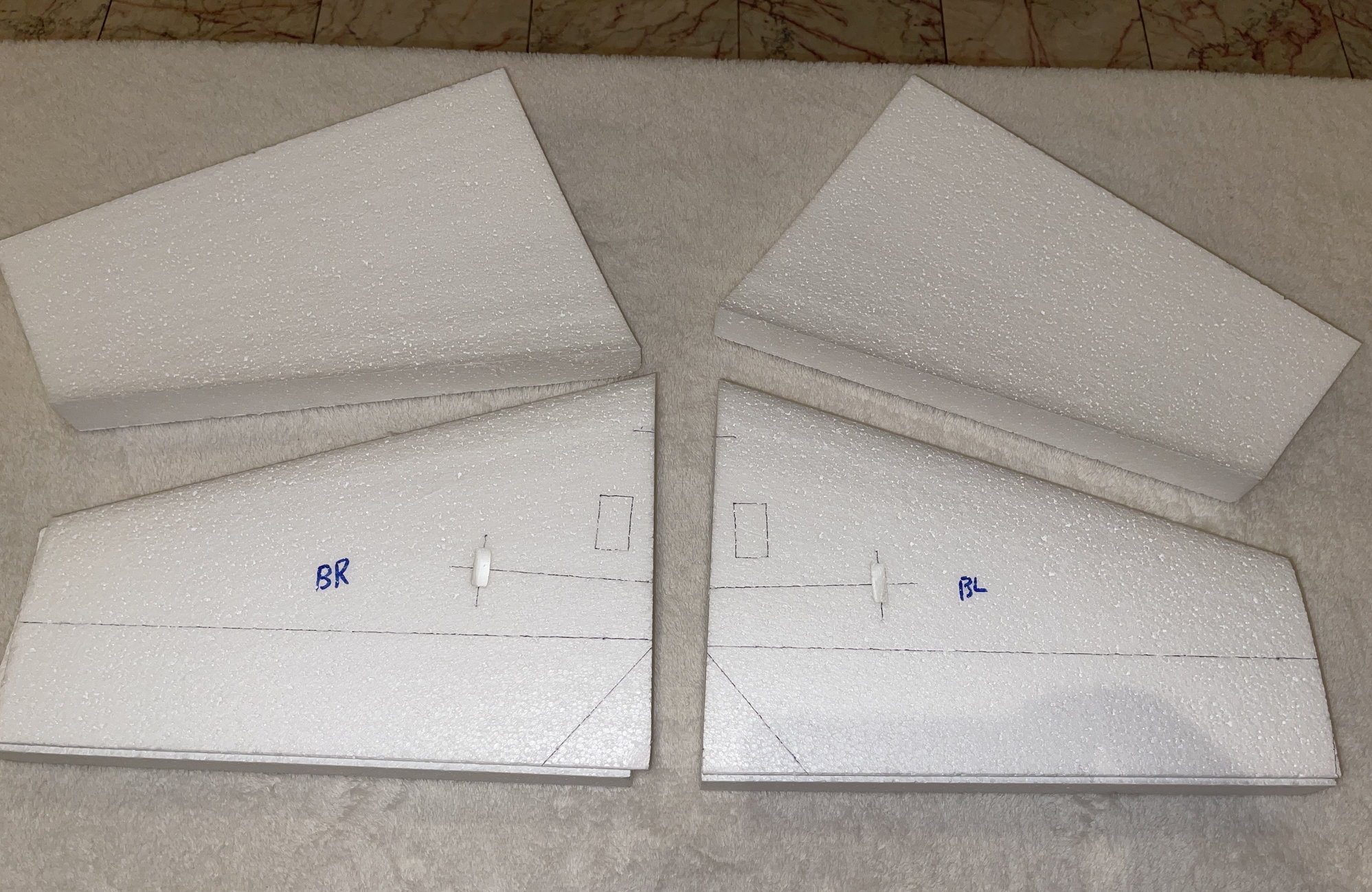
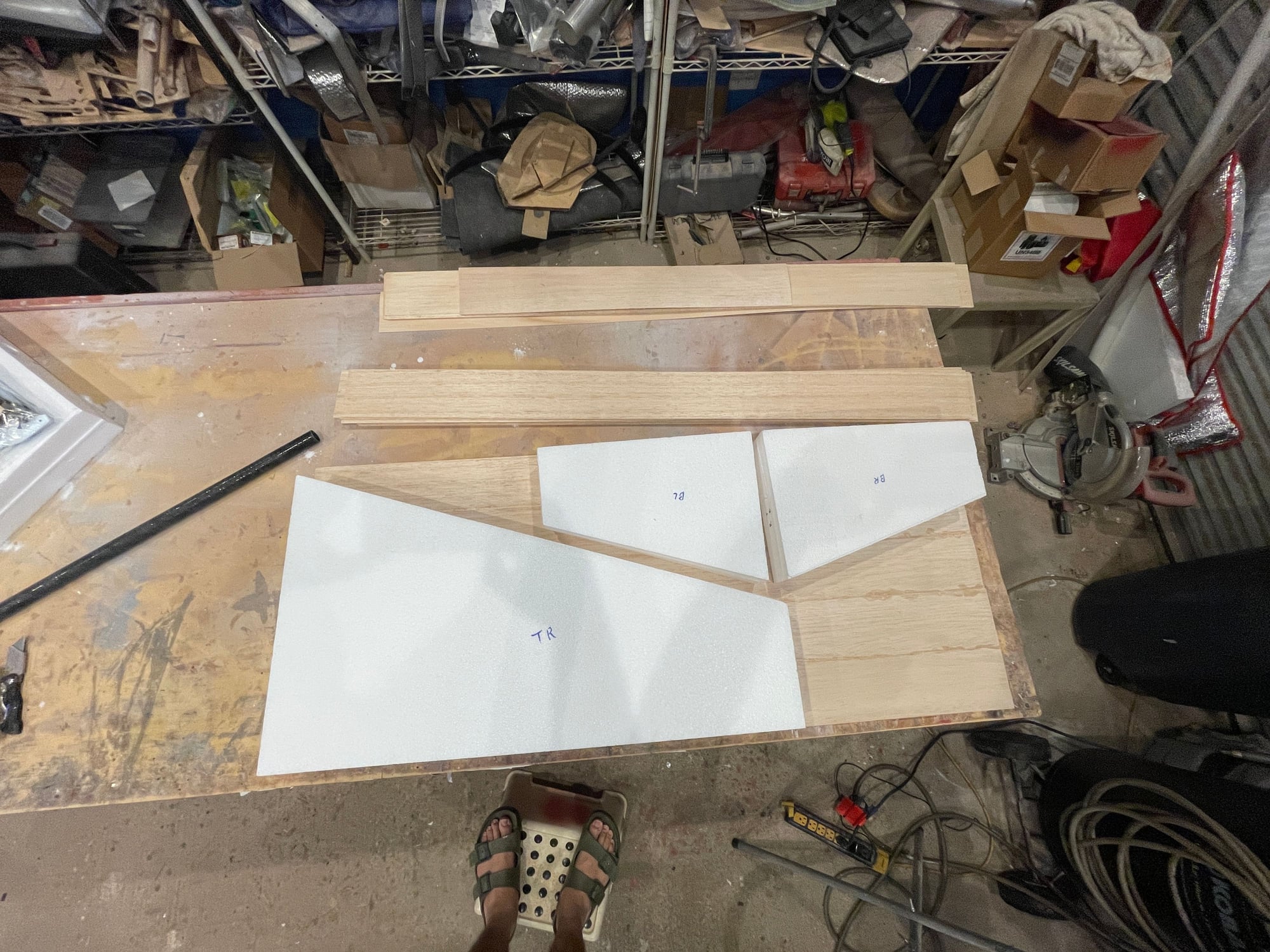
The foam shucks are all marked Top left and Top Right and Bottom left and Bottom right.
the stabs already have cutout foam for the stab tube phenolic balsa supports.
Bottom of stabs
Bottom of stabs, again, showing the servo location and the elevators hinge line.
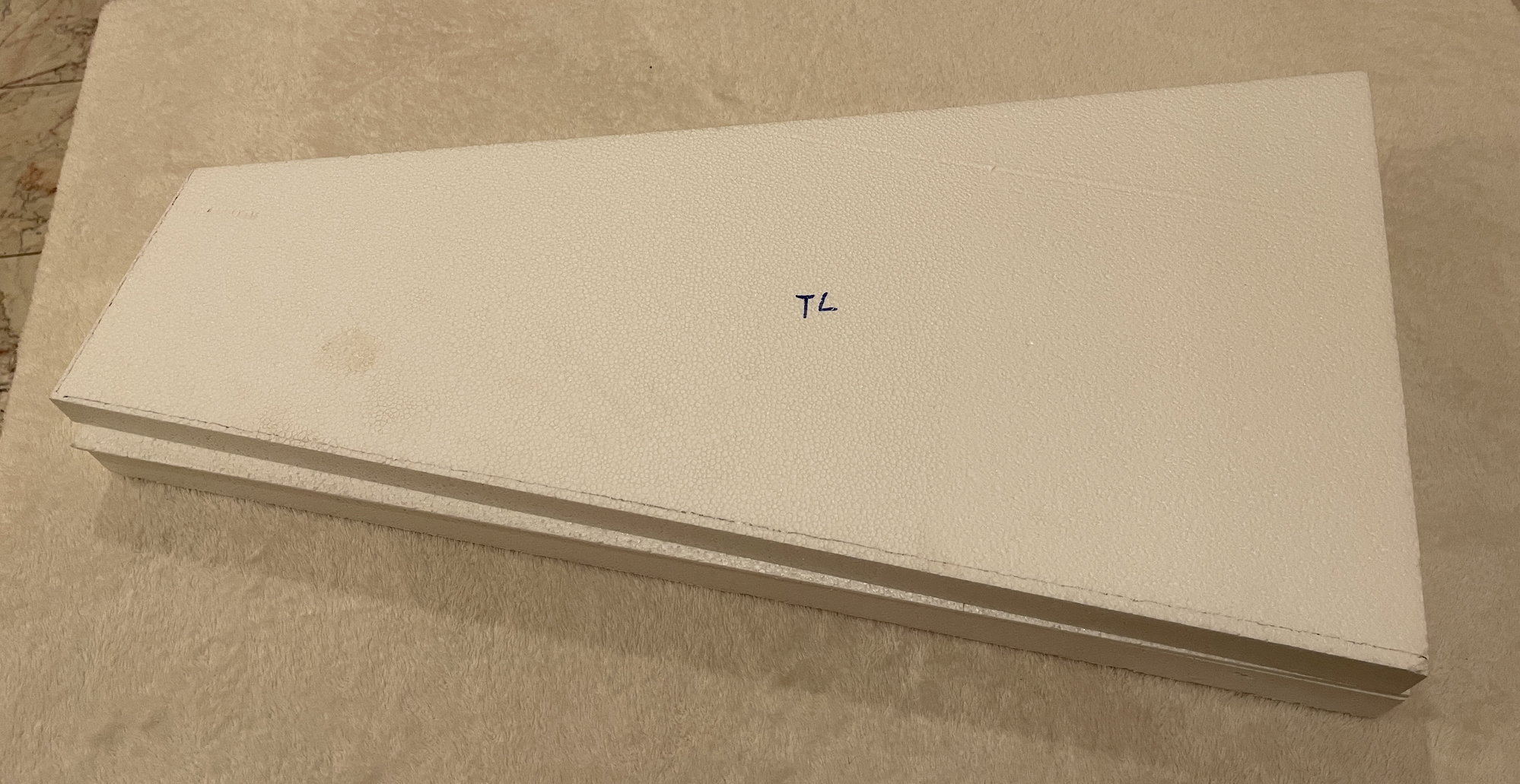
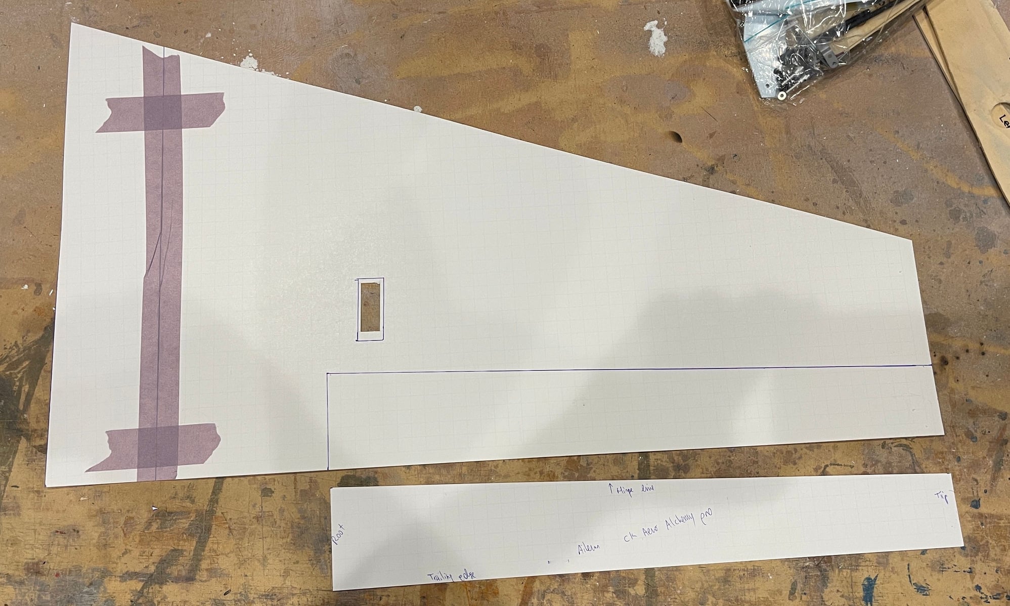
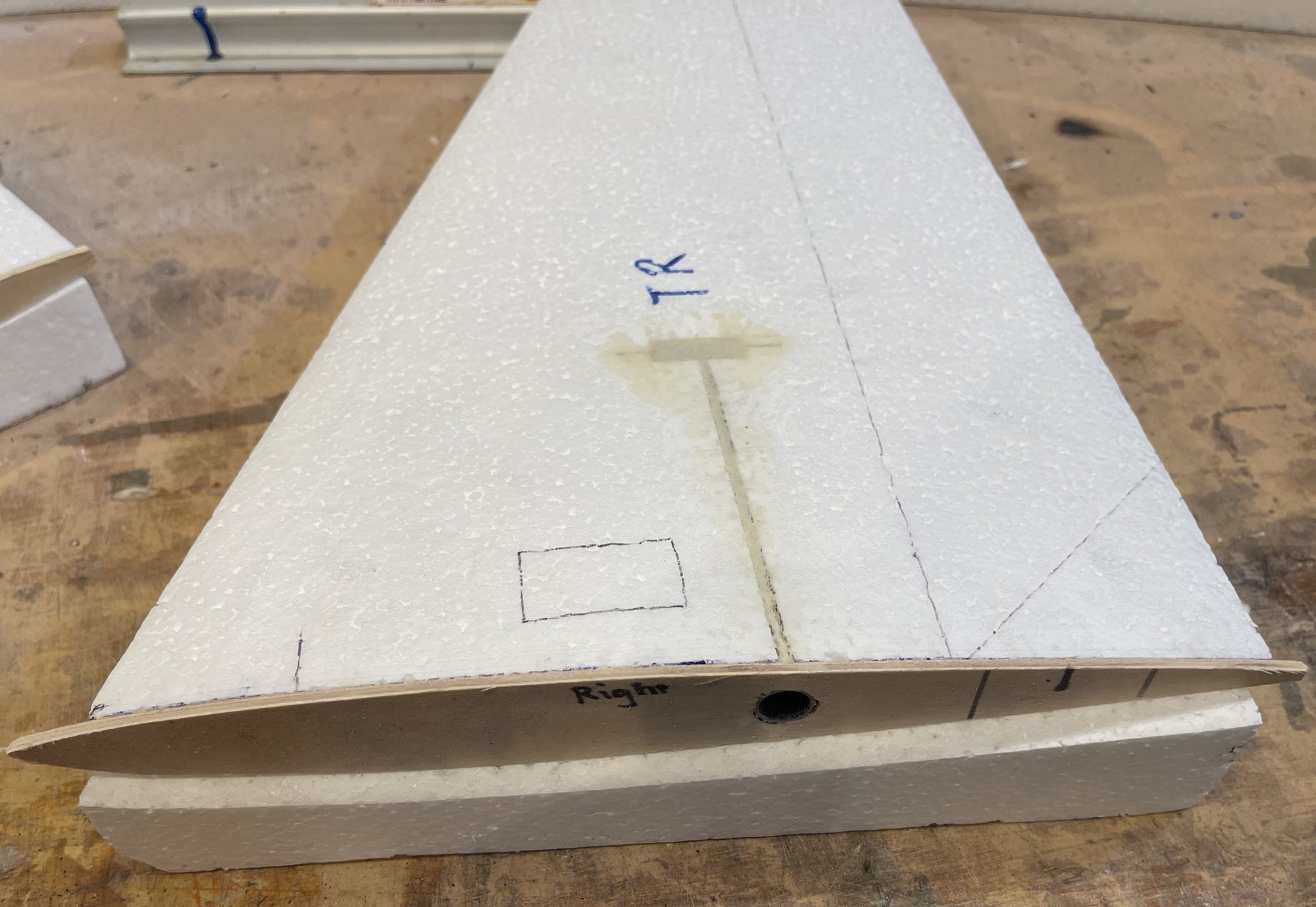
Wing Shucks are also labelled TL, TR, BL, BR. I did mark the roots of all the wings as well with a Sharpie to depict side and surface.
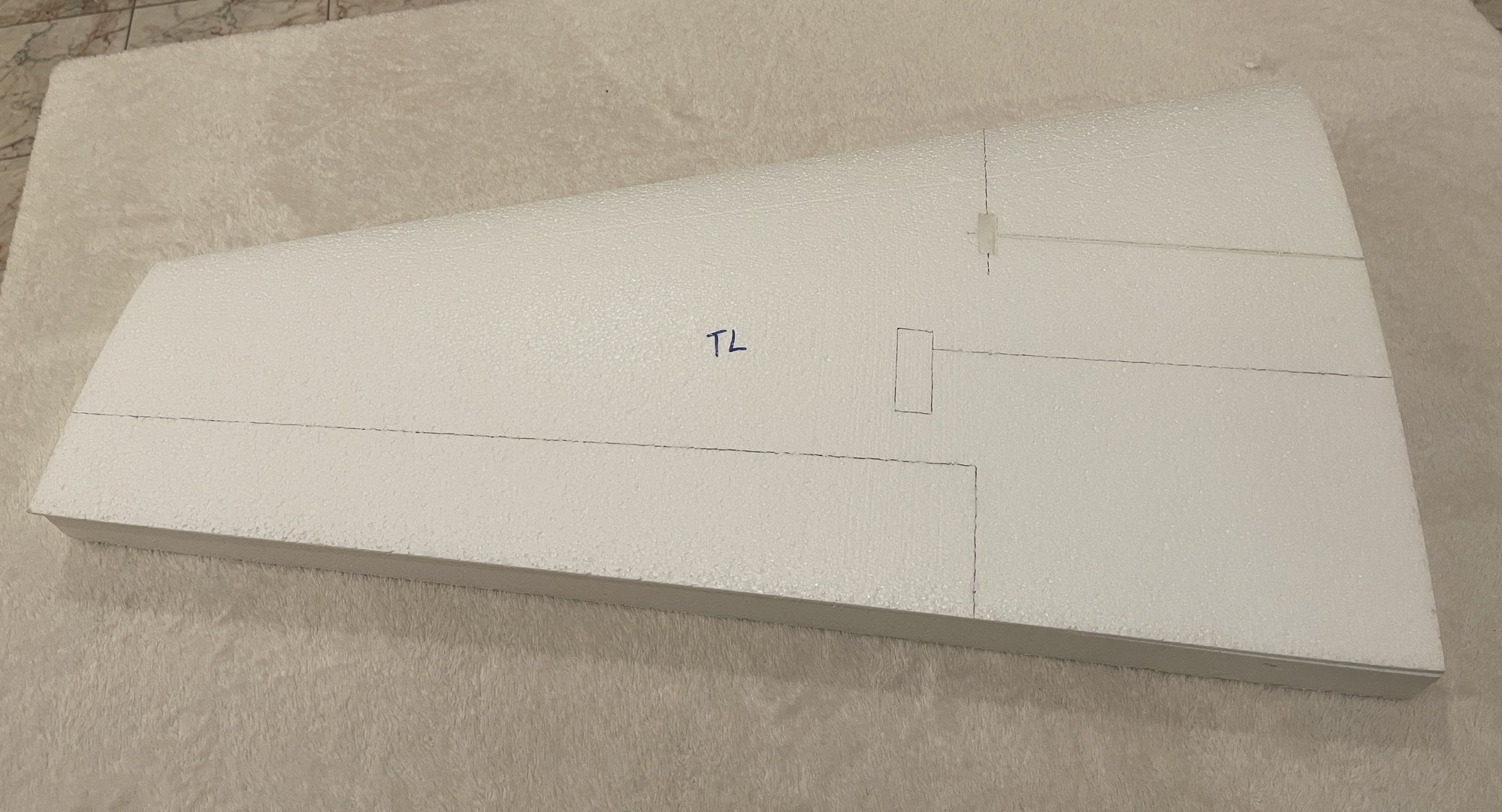
This again shows the position of the aileron and servo cutout area. Does not get better than that.
My questions:
For the hinge Line, what size balsa sticks should I use?
The for hinge line balsa, should I use low density, medium density, or high density balsa?
for the sheeting, using 1/16th sheets, I have about 50 sheets that are 3" by 48". I can sort them out based on weight. Which density should I use on the wings and the stabs? light, medium, or heavier?
first, I was extremely & pleasantly surprised to remove the shuck from both the wing and stabs and see that the hinge line and servo box area was already marked out!! this makes it so much easier. Thank you so much Bryan!!
Some pictures and then the questions:
The foam shucks are all marked Top left and Top Right and Bottom left and Bottom right.
the stabs already have cutout foam for the stab tube phenolic balsa supports.
Bottom of stabs
Bottom of stabs, again, showing the servo location and the elevators hinge line.
Wing Shucks are also labelled TL, TR, BL, BR. I did mark the roots of all the wings as well with a Sharpie to depict side and surface.
This again shows the position of the aileron and servo cutout area. Does not get better than that.
My questions:
For the hinge Line, what size balsa sticks should I use?
The for hinge line balsa, should I use low density, medium density, or high density balsa?
for the sheeting, using 1/16th sheets, I have about 50 sheets that are 3" by 48". I can sort them out based on weight. Which density should I use on the wings and the stabs? light, medium, or heavier?
05-02-2022, 10:05 AM
#3
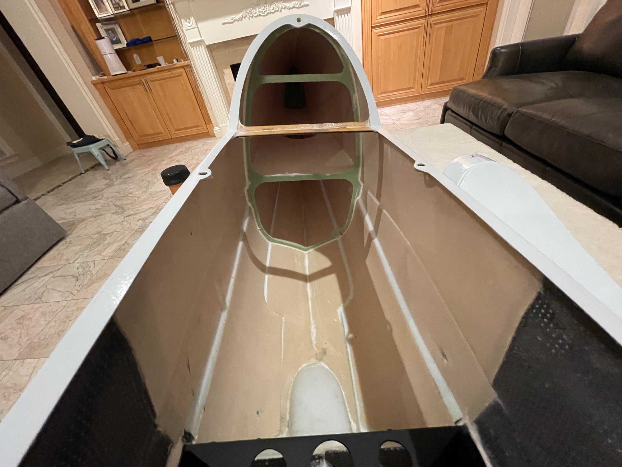
Some pictures of the fuselage:
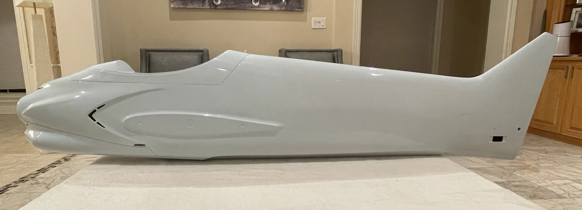
left sided view of the fusleage with the hatch area installed.
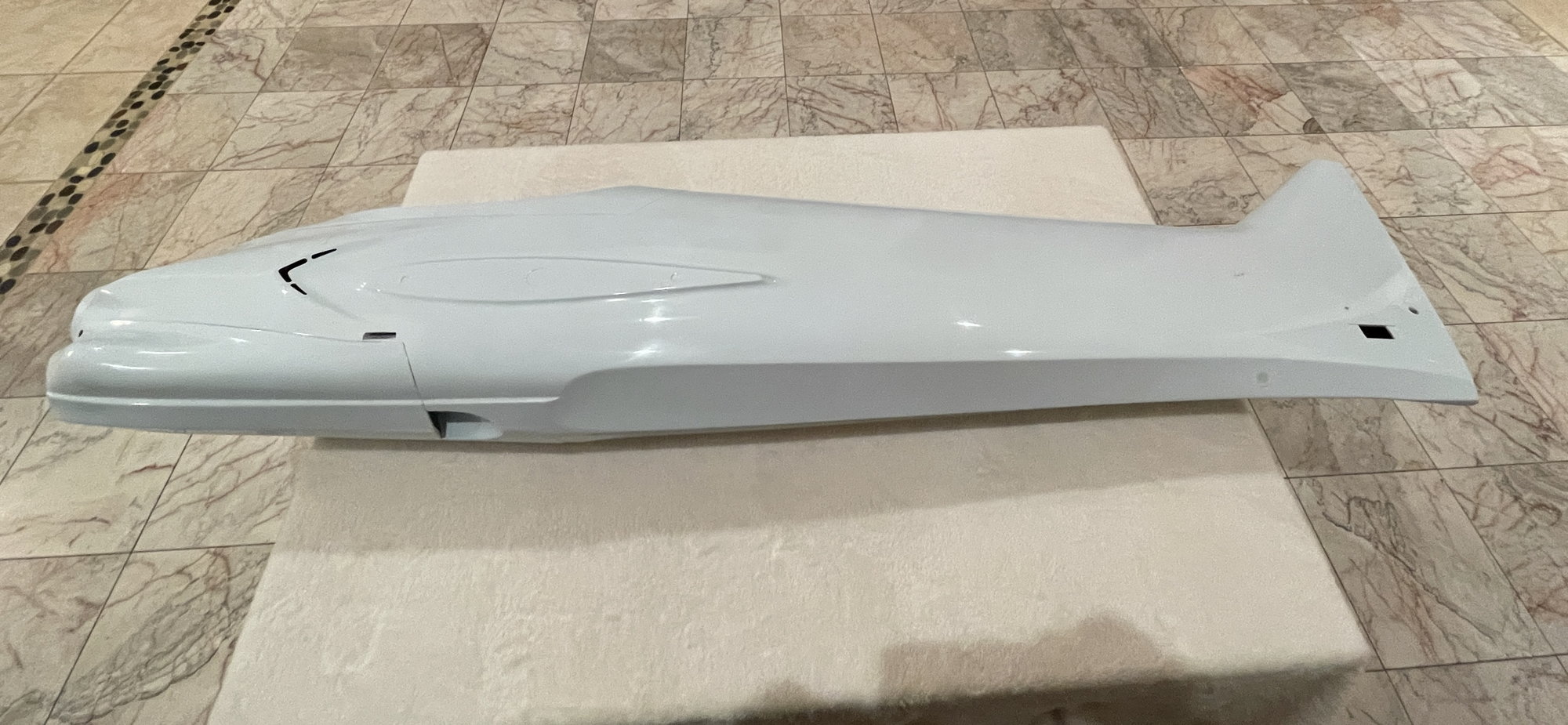
bottom view of the fuselage
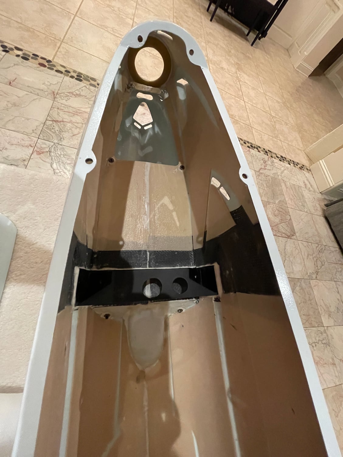
motor bay area
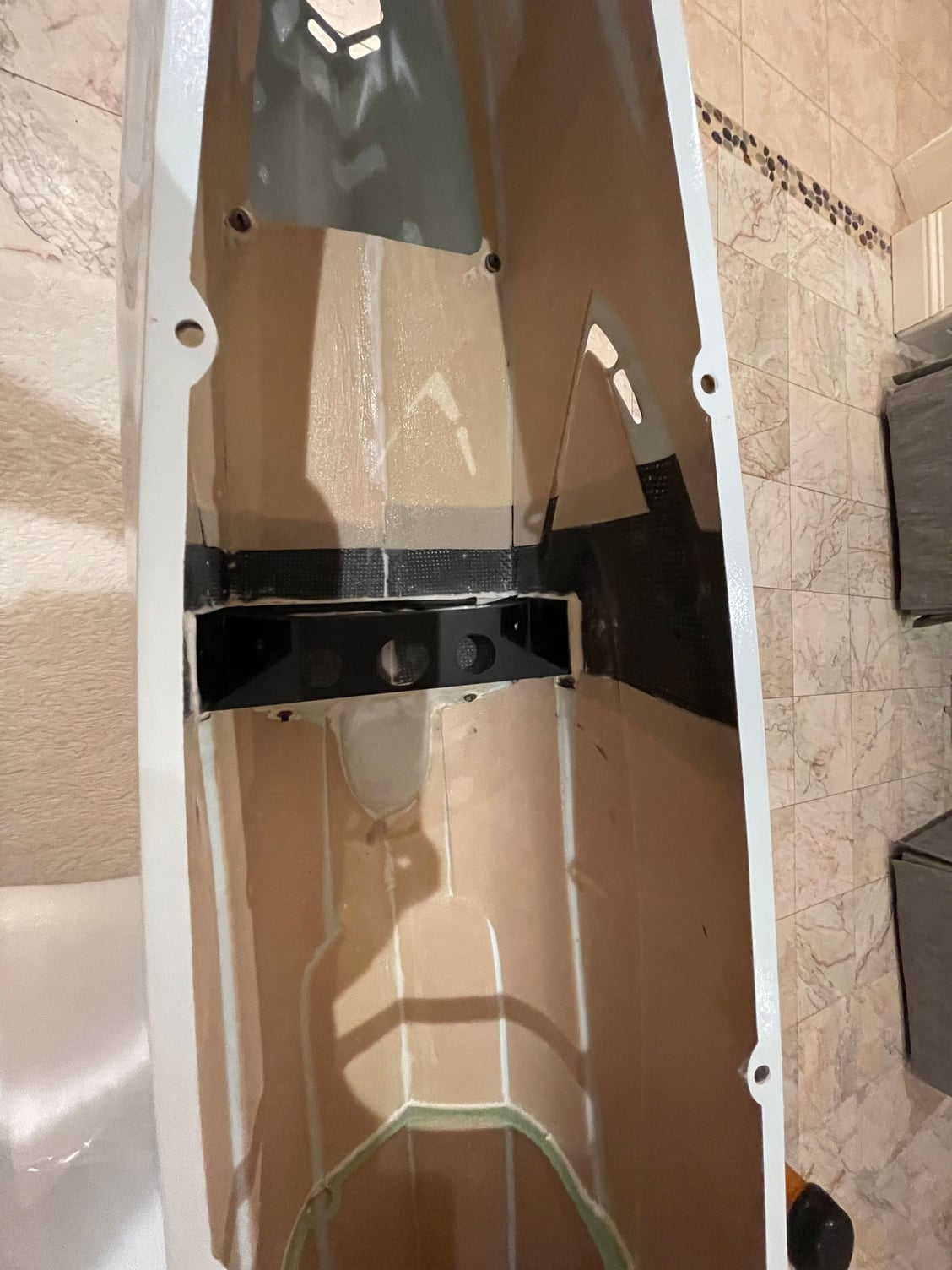
view of the landing gear installation points
mid fuselage bay area

inside of the rear of the fuselage
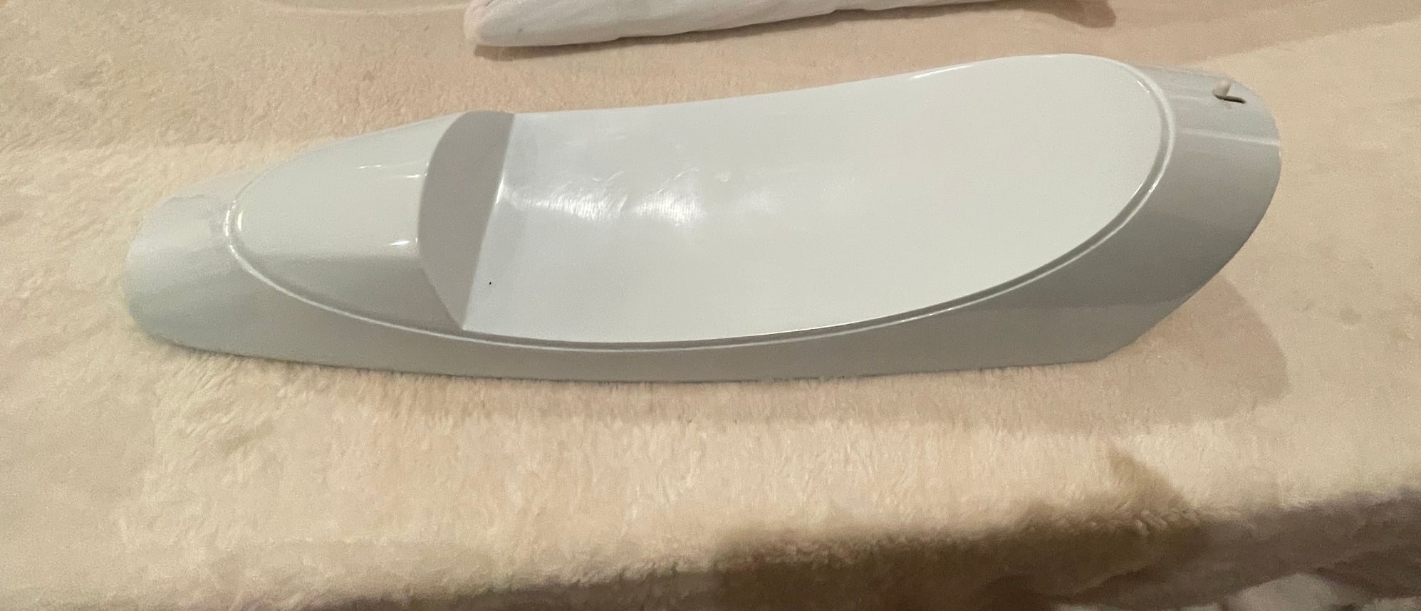
top of the hatch
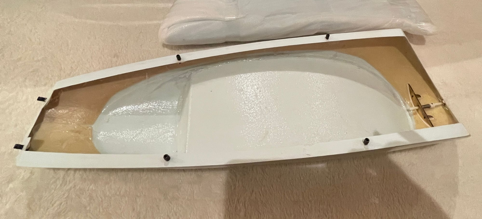
bottom view of the hatch

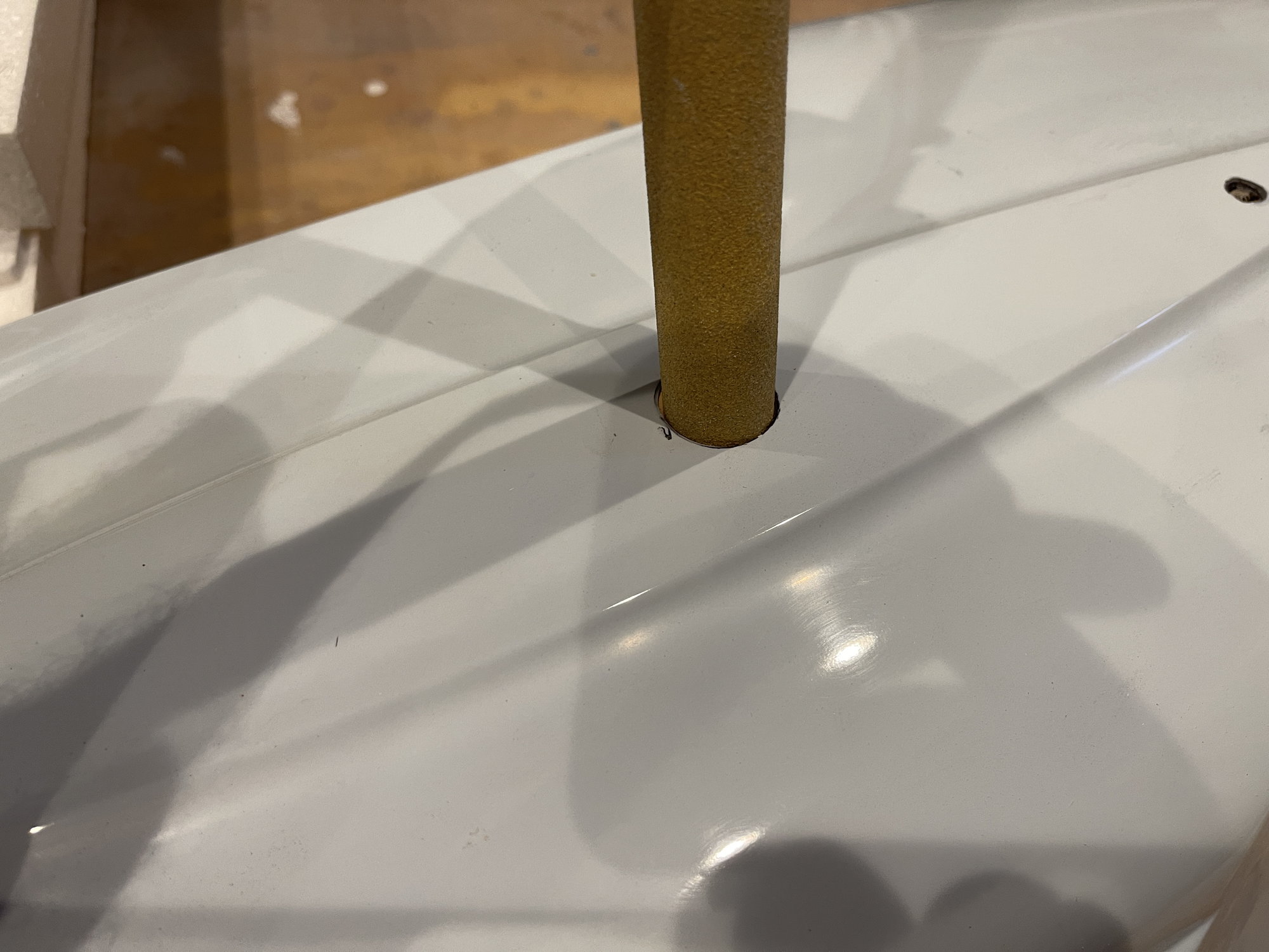
left side of fuse, showing the installed stab tube in the tail as well as cut out for the rudder servo and the small hole for the front stab stabilizer pin.
As you can see from these pictures, the inside is as beautiful as the outside. the joints and the glue is impeccable. Defintitely well built and designed.
left sided view of the fusleage with the hatch area installed.
bottom view of the fuselage
motor bay area
view of the landing gear installation points
mid fuselage bay area
inside of the rear of the fuselage
top of the hatch
bottom view of the hatch
left side of fuse, showing the installed stab tube in the tail as well as cut out for the rudder servo and the small hole for the front stab stabilizer pin.
As you can see from these pictures, the inside is as beautiful as the outside. the joints and the glue is impeccable. Defintitely well built and designed.
 05-11-2022, 02:53 AM
#5
Hope to get started soon. My shop has a CARF P47 that i was changing out the gear doors from pneumatic to an actuator. After installing the actuator, I did not like the sequence timing and just overall, the safety of these actuators, which do not give at all, and are too slow. SO i will remove the actuators and the gear doors, then clear the shop and clean it out well. then I can start on this pattern airplane.
My 1st order of business is to glue in the phneolics into the wings and stabs.
this will require making balsa blocks that will key into the cut outs so they fit perfectly and snug, with minimal gaps, then to core out the hole for the phenolic on the balsa block.
My 1st order of business is to glue in the phneolics into the wings and stabs.
this will require making balsa blocks that will key into the cut outs so they fit perfectly and snug, with minimal gaps, then to core out the hole for the phenolic on the balsa block.
05-13-2022, 06:51 PM
#6
was able to finish clearing my building table, then I spent a good amount of time sanding down any glue spots or paint to make it as flat as possible. then I also re did the straight edge, to make sure the length of the table was as flat as possible.
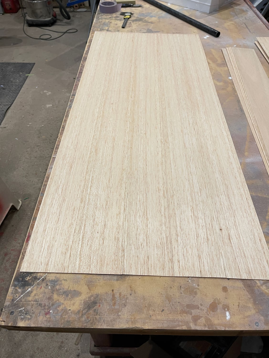
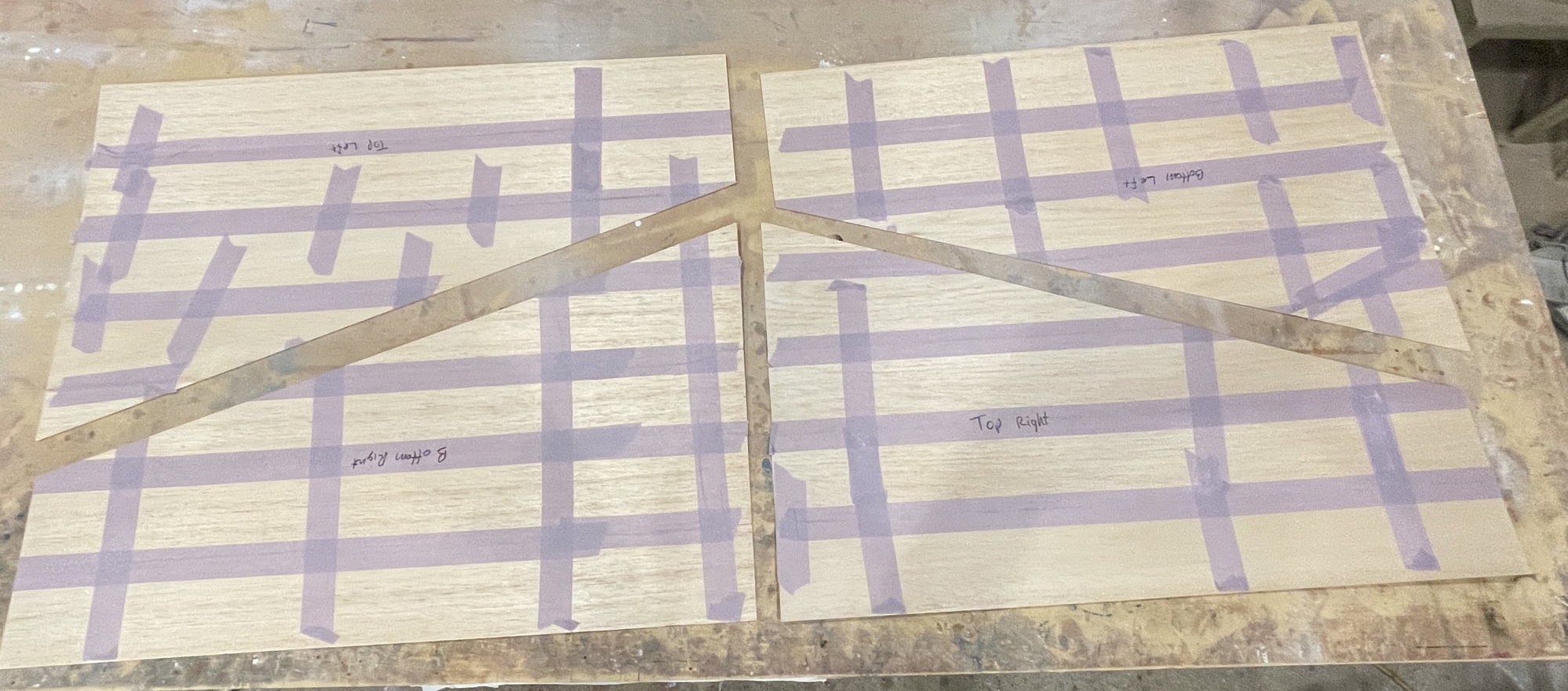
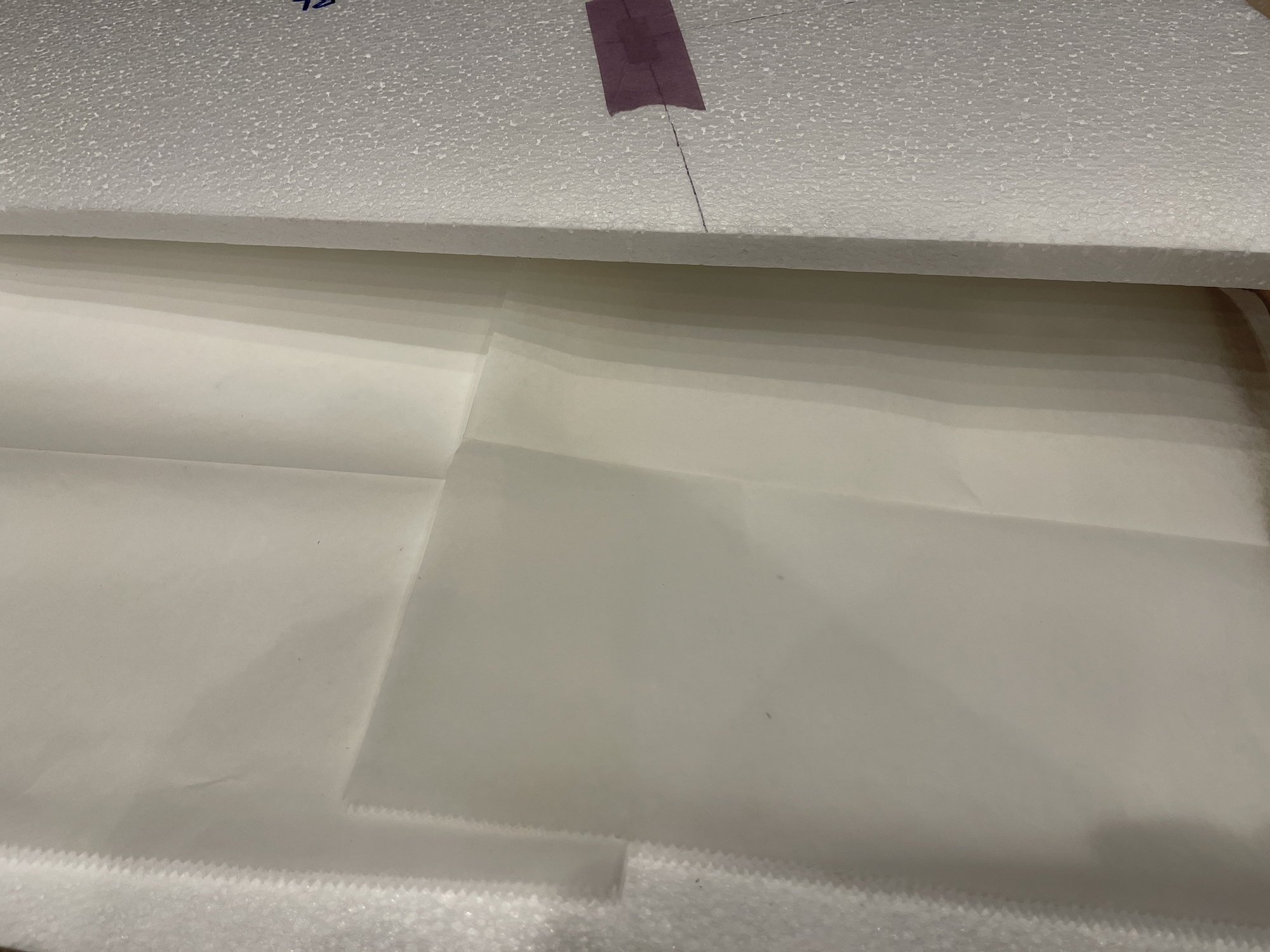
Following this, I made the skins for the wings and the stabs.
planning of the sheets
from one sheet, I was able to make the skin for one side of the wing and both sides of one of the stabs.
all 4 skins for the wings
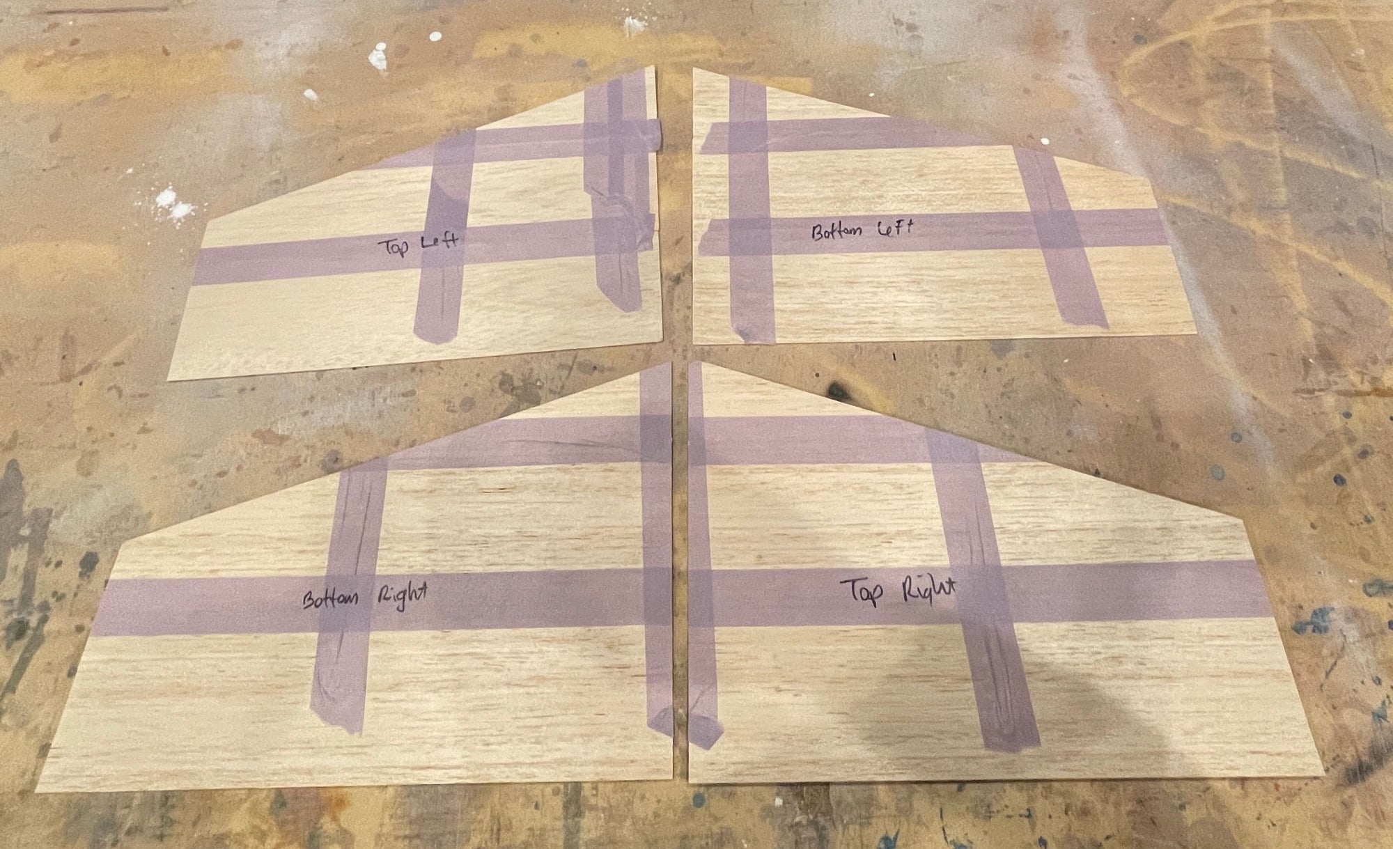
all 4 balsa sheeting skins for the stabs
I am using the 1/16th high quality balsa. Not a single knot on any of the balsa sheets.
tomorrow, I will weigh each skin.
Albeit, the tape is on each skin, and I will keep the tape on until after I vacuum bag the wings and stabs. The tape help prevents bleed thru of the resin to the shuck.
Following this, I made the skins for the wings and the stabs.
planning of the sheets
from one sheet, I was able to make the skin for one side of the wing and both sides of one of the stabs.
all 4 skins for the wings
all 4 balsa sheeting skins for the stabs
I am using the 1/16th high quality balsa. Not a single knot on any of the balsa sheets.
tomorrow, I will weigh each skin.
Albeit, the tape is on each skin, and I will keep the tape on until after I vacuum bag the wings and stabs. The tape help prevents bleed thru of the resin to the shuck.
05-13-2022, 06:57 PM
#7
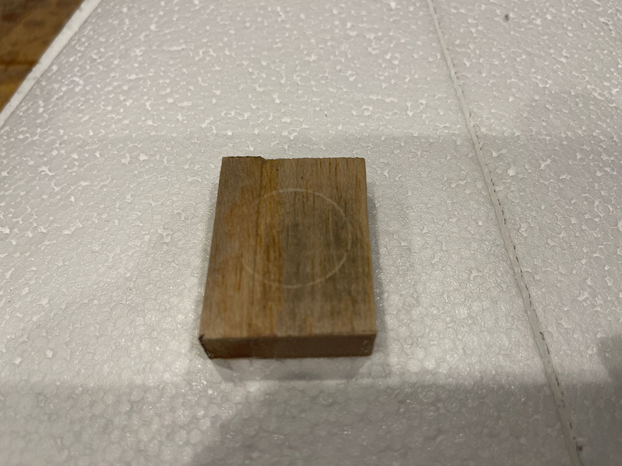
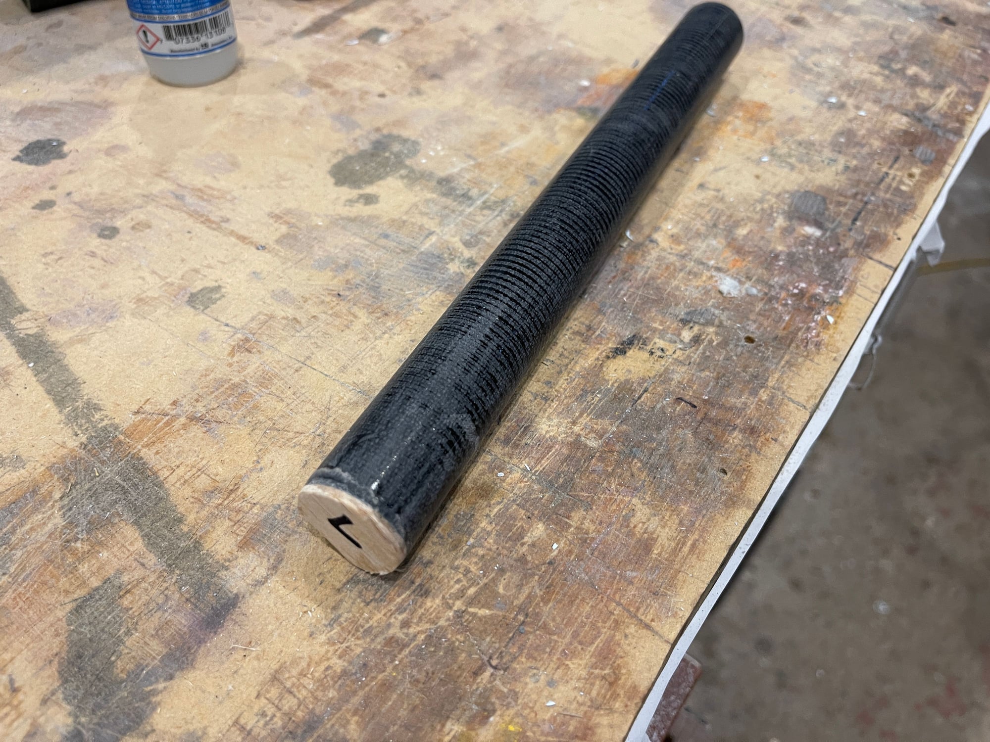
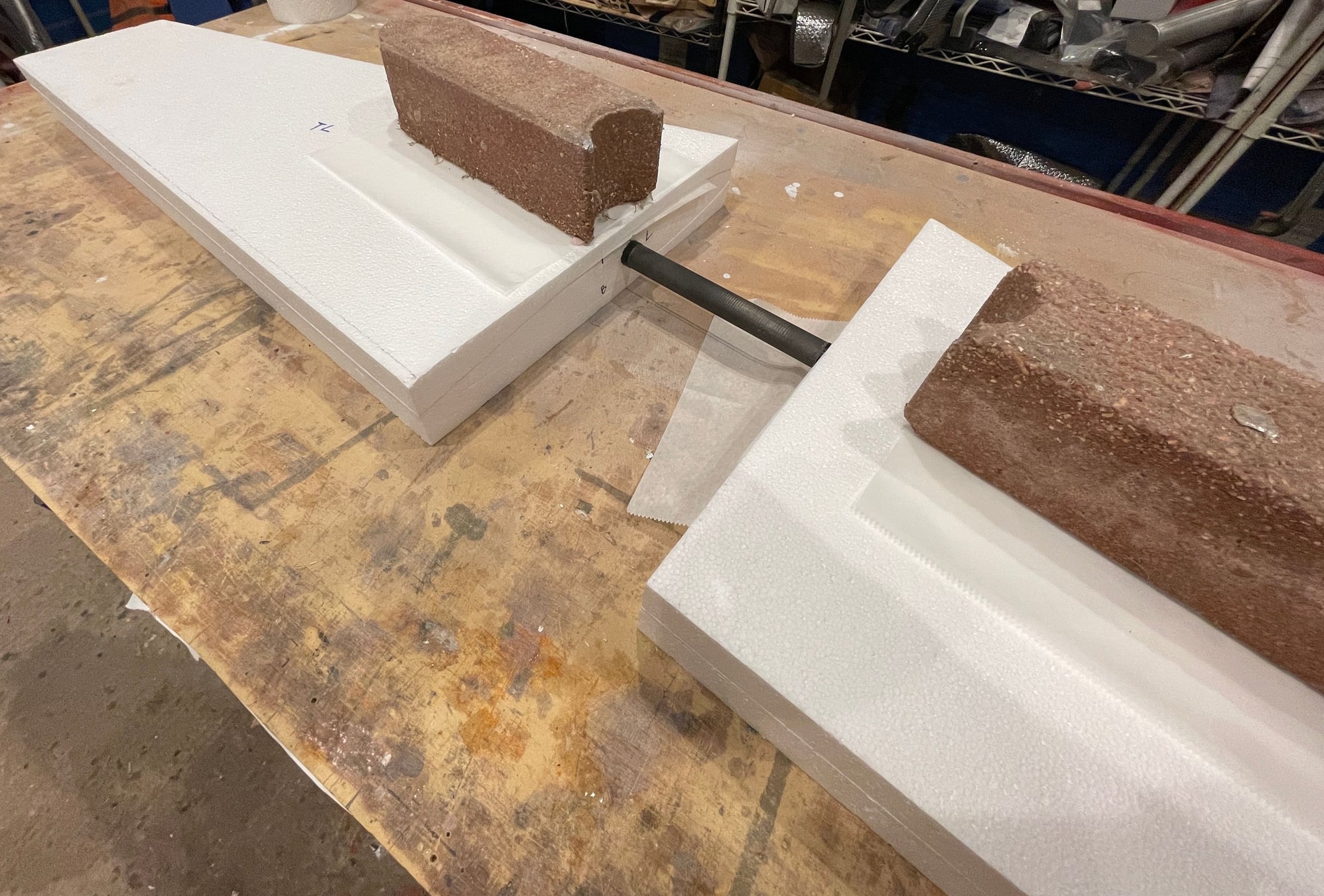
Starting to work on the wing phenolic tube end of tube balsa support blocks.
i measured the wing tube phenolic, and it is 1" in diameter .
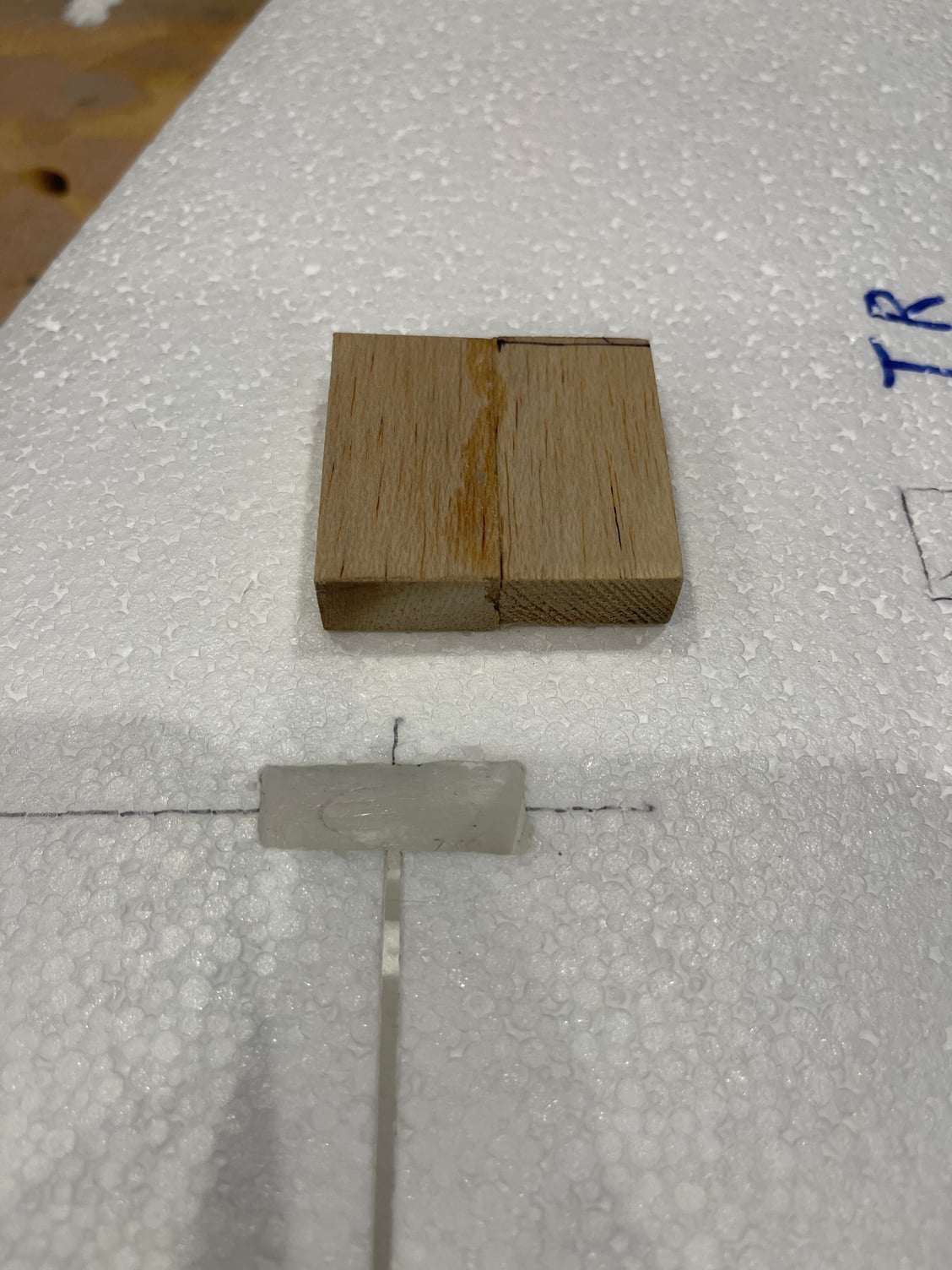
this is 1/2" thick balsa
after trimming it to fit the slot.

inserted thru all the way.
the socket
inserting the phenolic tube til it bottoms out, then I twist onto the balsa block
Here is the indentation from the phenolic tube.

using tube as a template
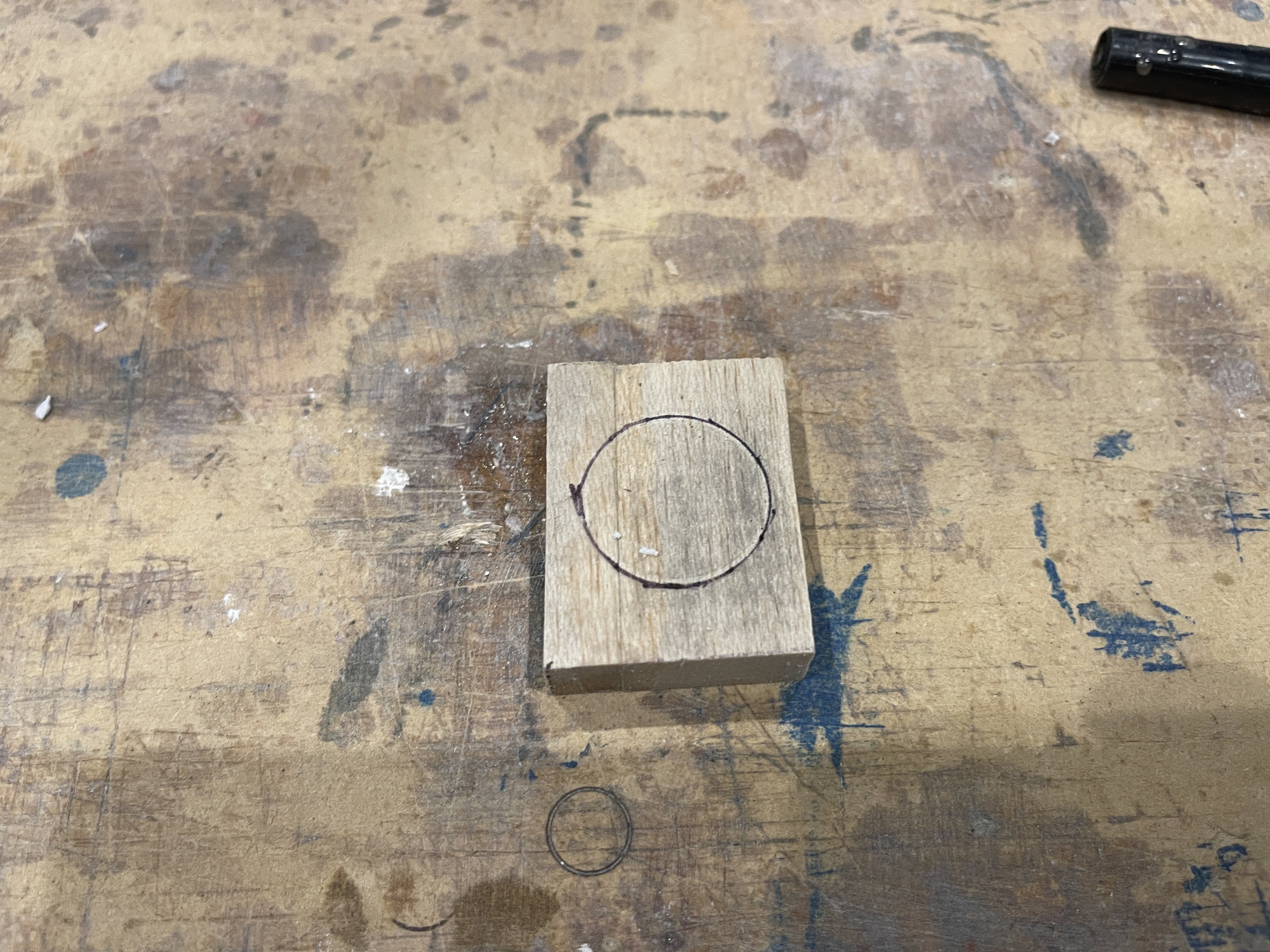
i then traced the tube over the block
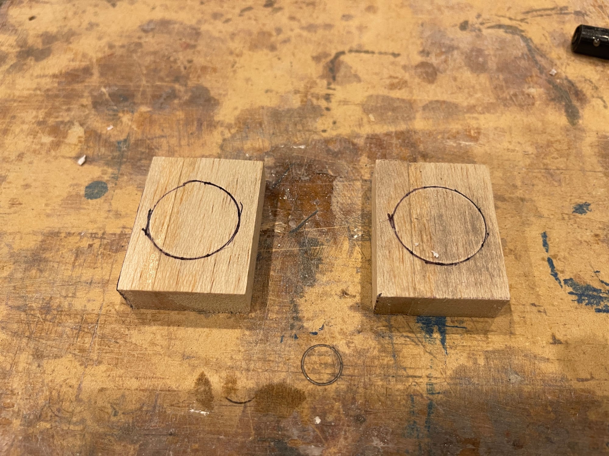
both blocks ready to be drilled out with a 1" forstner bit.
i measured the wing tube phenolic, and it is 1" in diameter .
this is 1/2" thick balsa
after trimming it to fit the slot.
inserted thru all the way.
the socket
inserting the phenolic tube til it bottoms out, then I twist onto the balsa block
Here is the indentation from the phenolic tube.
using tube as a template
i then traced the tube over the block
both blocks ready to be drilled out with a 1" forstner bit.
05-14-2022, 04:12 AM
#8
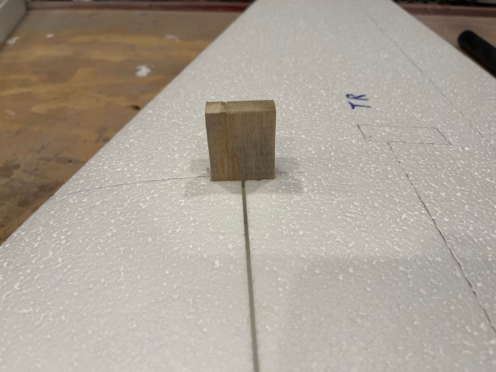
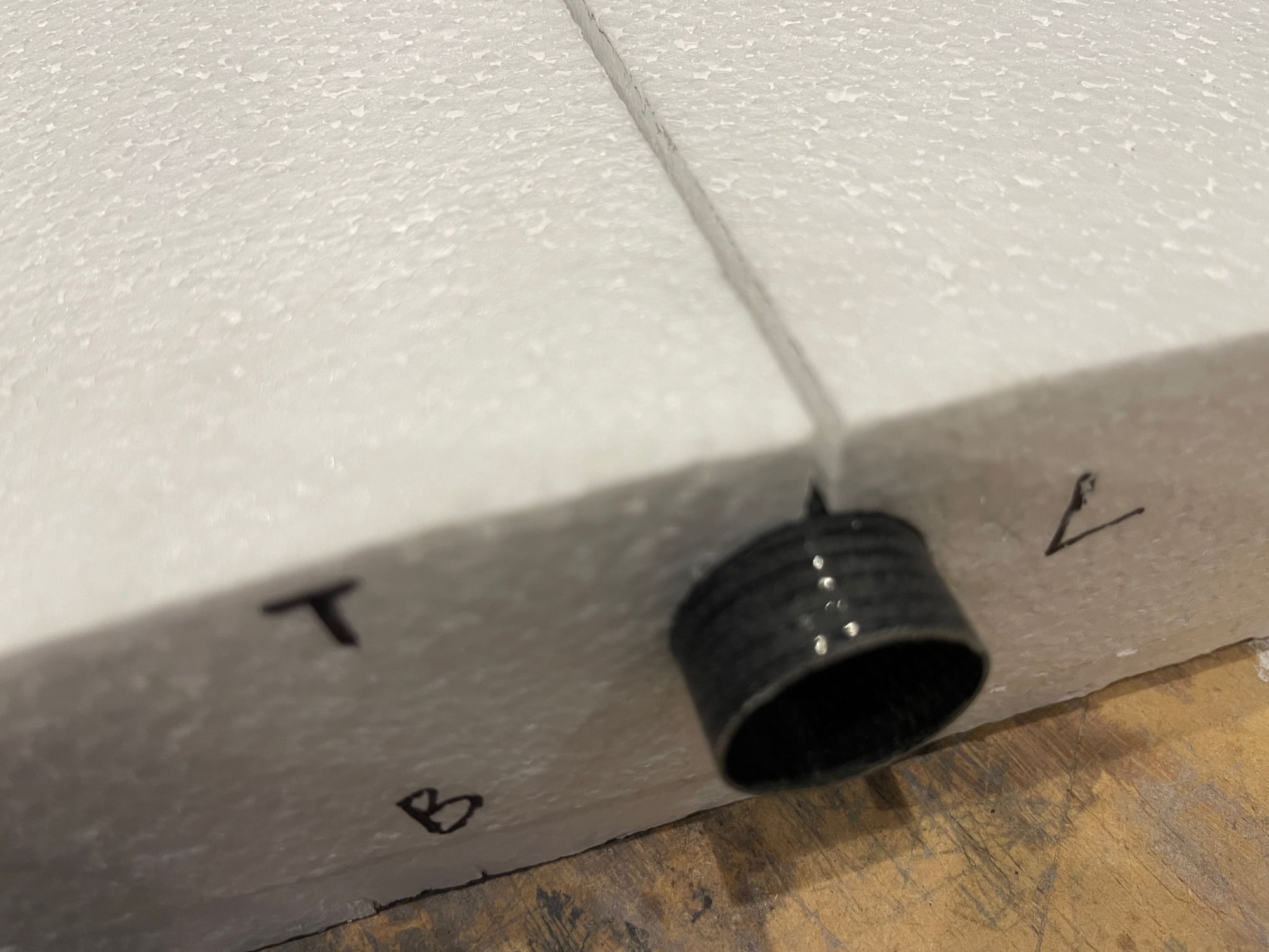
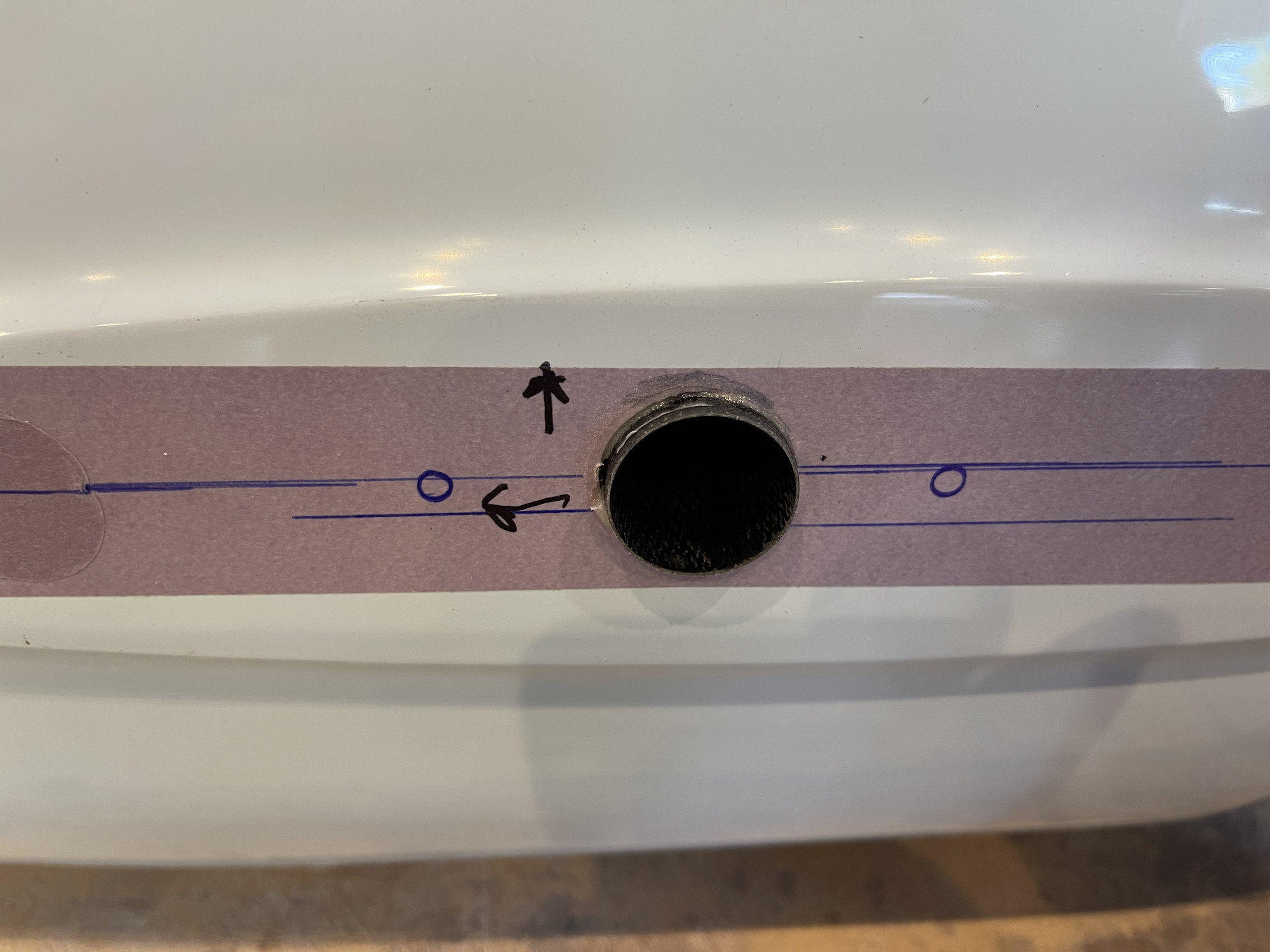
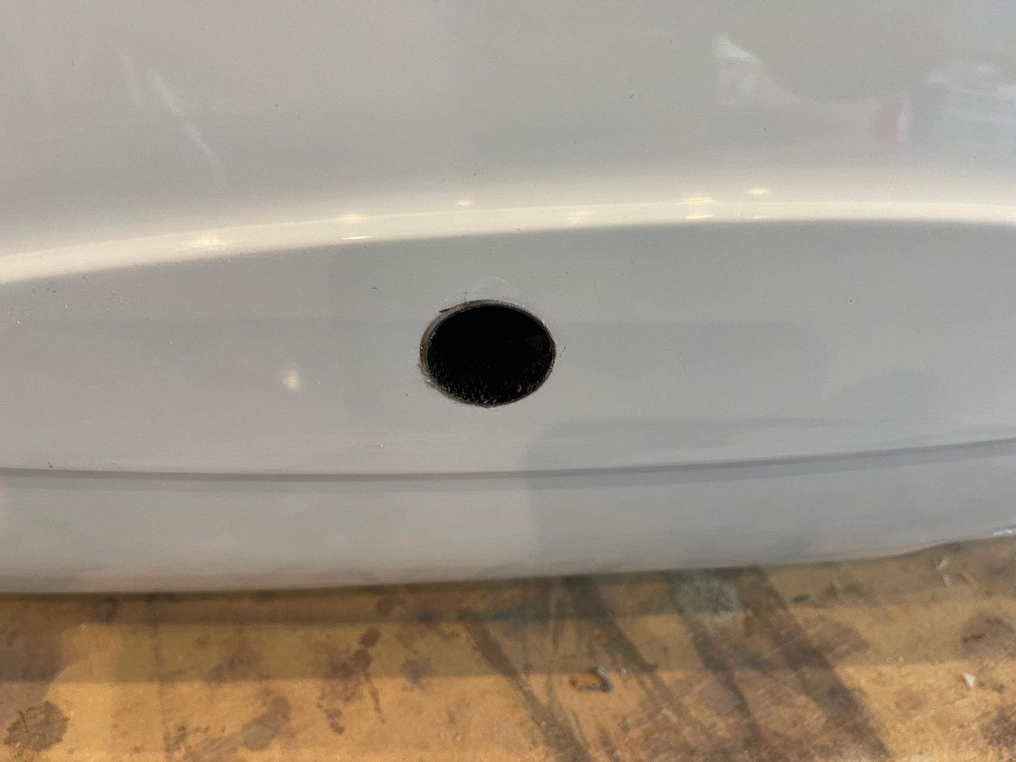
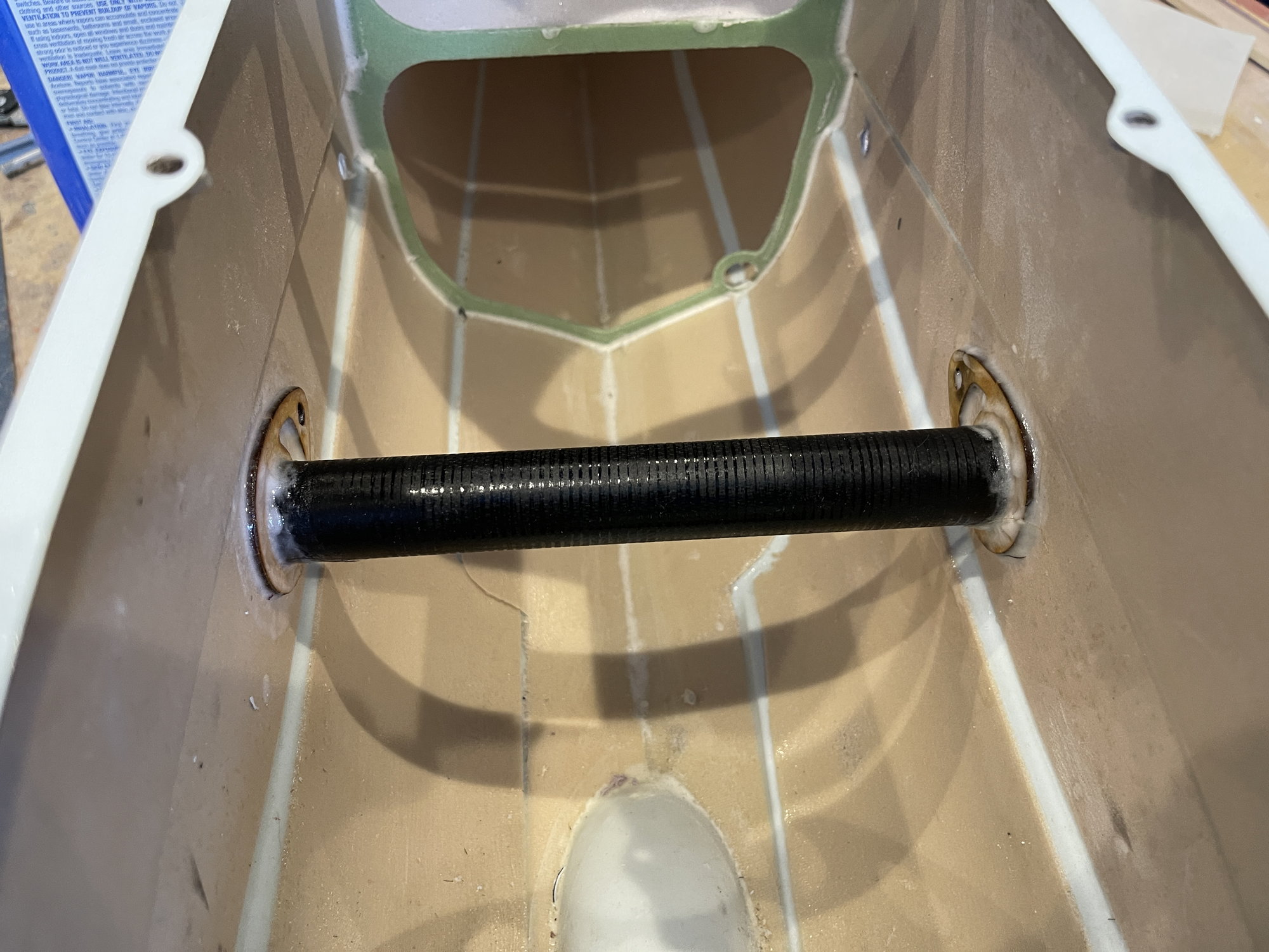
I did the cut outs in the fuselage sides for the wing tube phenolic:
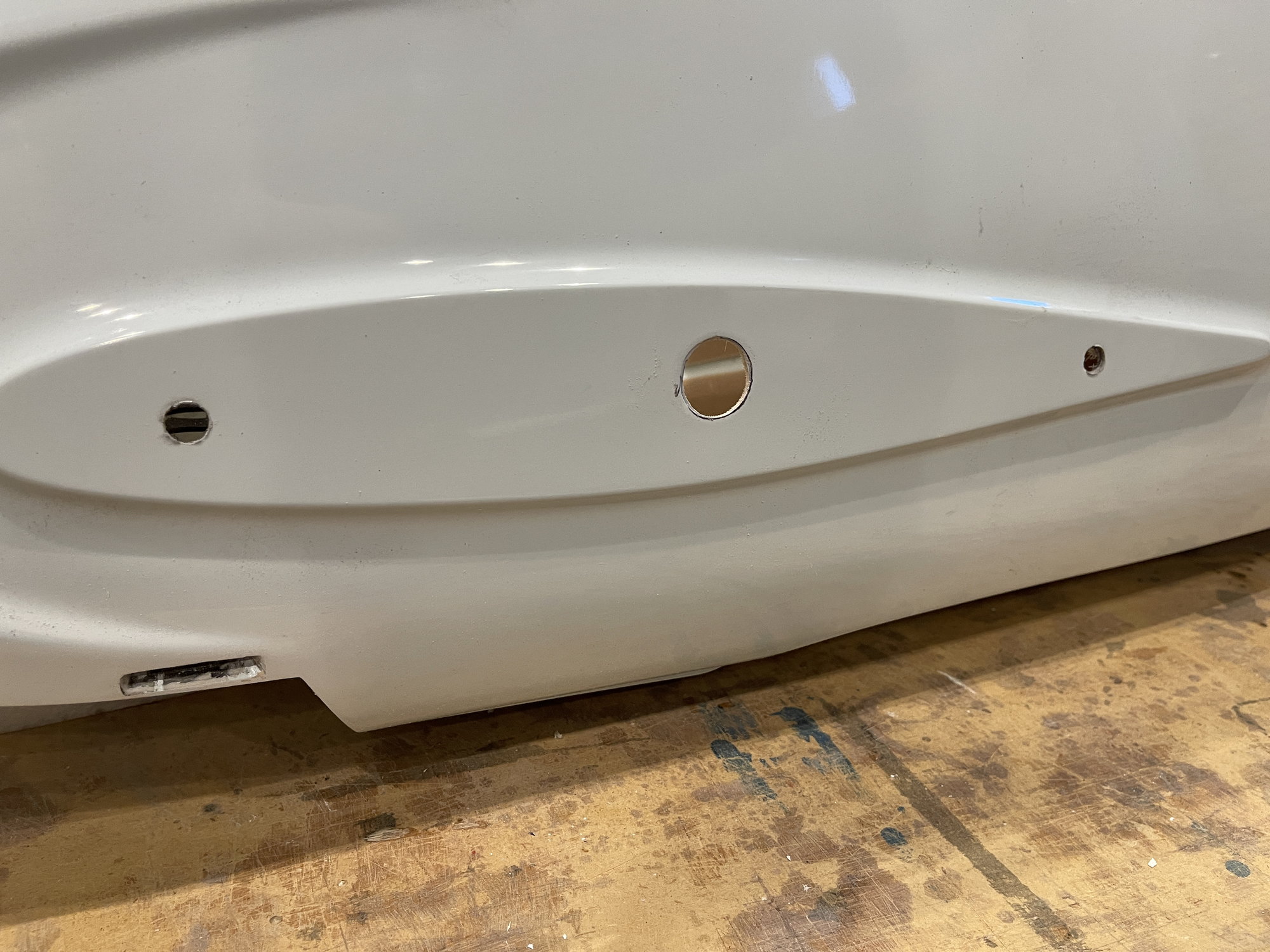
cut out hole for wing tube phenolic
then I used a 7/8" wood dowel, and wrapped the end with sand paper, and then i rounded out the hole:
making hole round
i genlty went back and forth, until I was able to get the phenolic in there, with a tight fit. I will also check that the wing tube goes in smoothly before I commit to glueing it in.
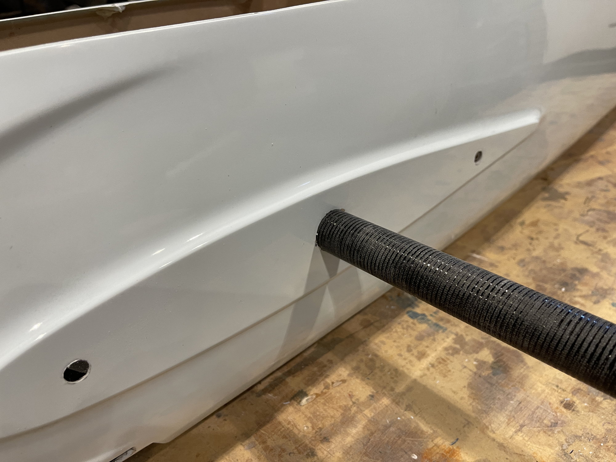
test of the fit
this is the inside look. NOT doing the glue fixation yet. Still have to make measurements. The ply doubler is not installed yet either.
I will do that once I am happy with the measurements.
inside view
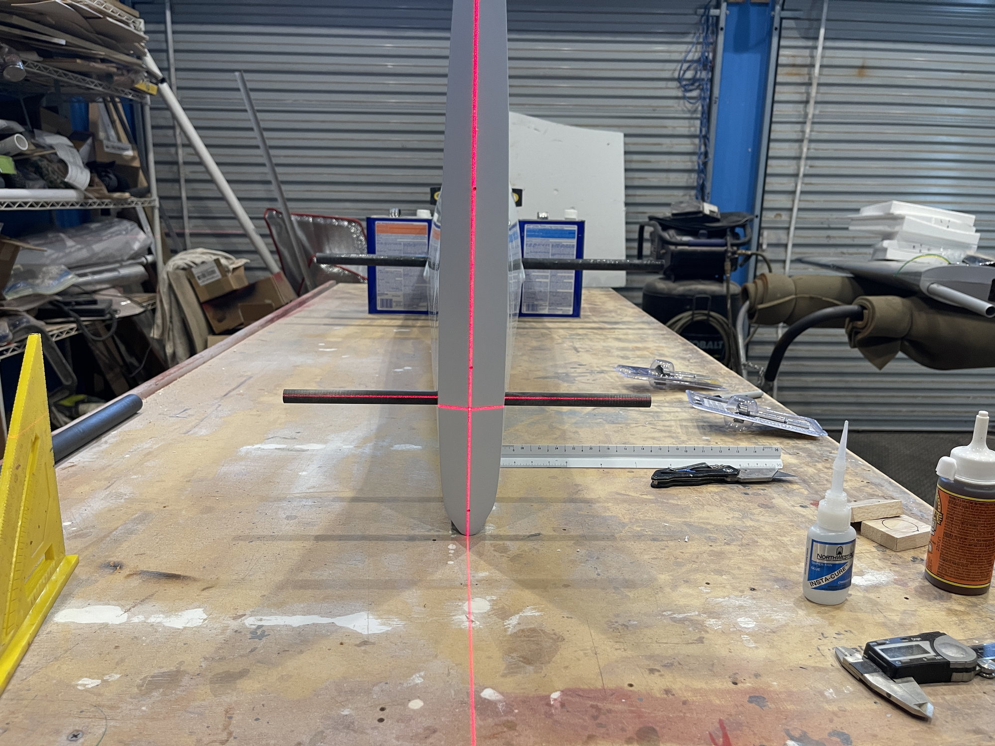
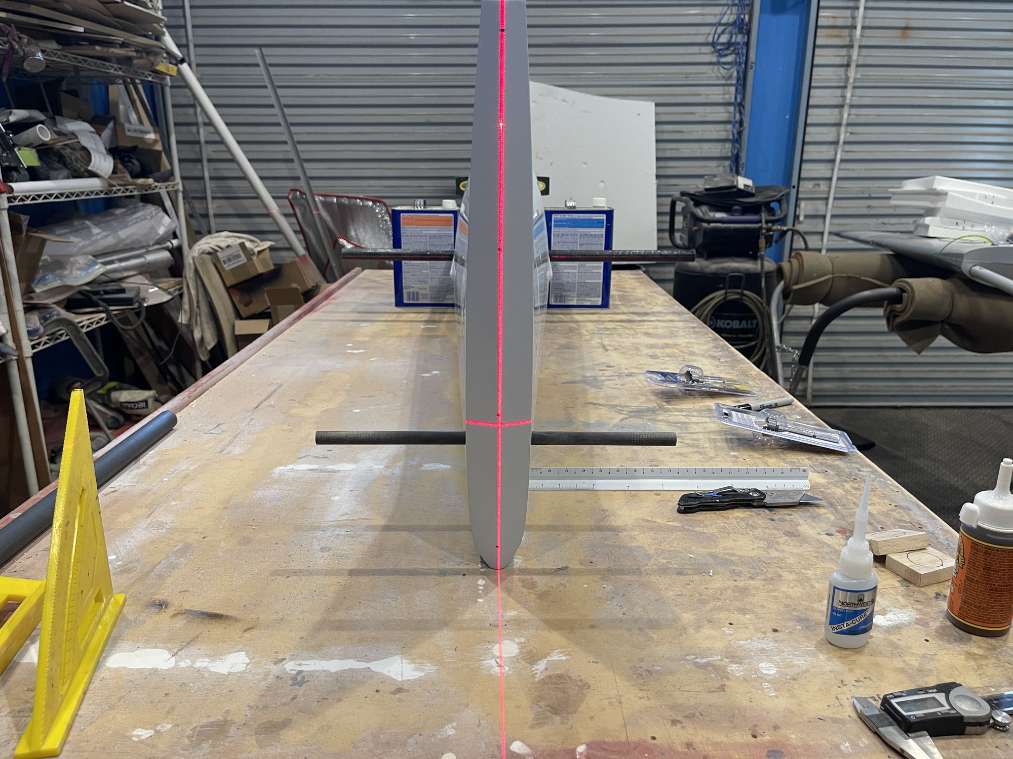
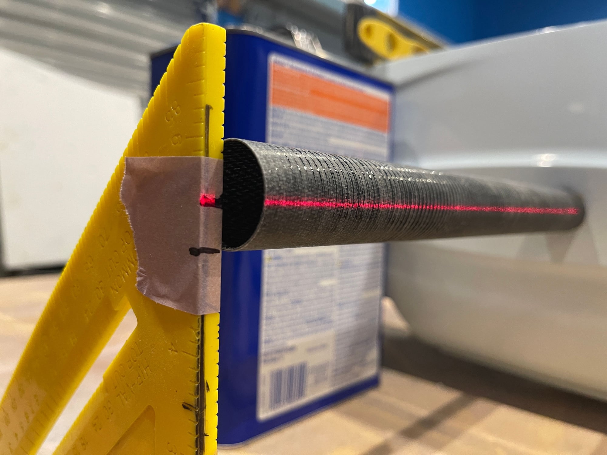
now, the next step, is to make measurements and assure the wing tube is aligned and in line with the stab tube in two planes.
I will use a laser light also.
Once I am happy that the wing tube is parallel to the stab tube from the rear view and also by making measurements, then I will glue it in.
Leaving now to a Jet Rally, but when I get home, I will continue.
I will also start to weigh everything so that I can document the weights.
cut out hole for wing tube phenolic
then I used a 7/8" wood dowel, and wrapped the end with sand paper, and then i rounded out the hole:
making hole round
i genlty went back and forth, until I was able to get the phenolic in there, with a tight fit. I will also check that the wing tube goes in smoothly before I commit to glueing it in.
test of the fit
this is the inside look. NOT doing the glue fixation yet. Still have to make measurements. The ply doubler is not installed yet either.
I will do that once I am happy with the measurements.
inside view
now, the next step, is to make measurements and assure the wing tube is aligned and in line with the stab tube in two planes.
I will use a laser light also.
Once I am happy that the wing tube is parallel to the stab tube from the rear view and also by making measurements, then I will glue it in.
Leaving now to a Jet Rally, but when I get home, I will continue.
I will also start to weigh everything so that I can document the weights.
05-14-2022, 05:33 PM
#9
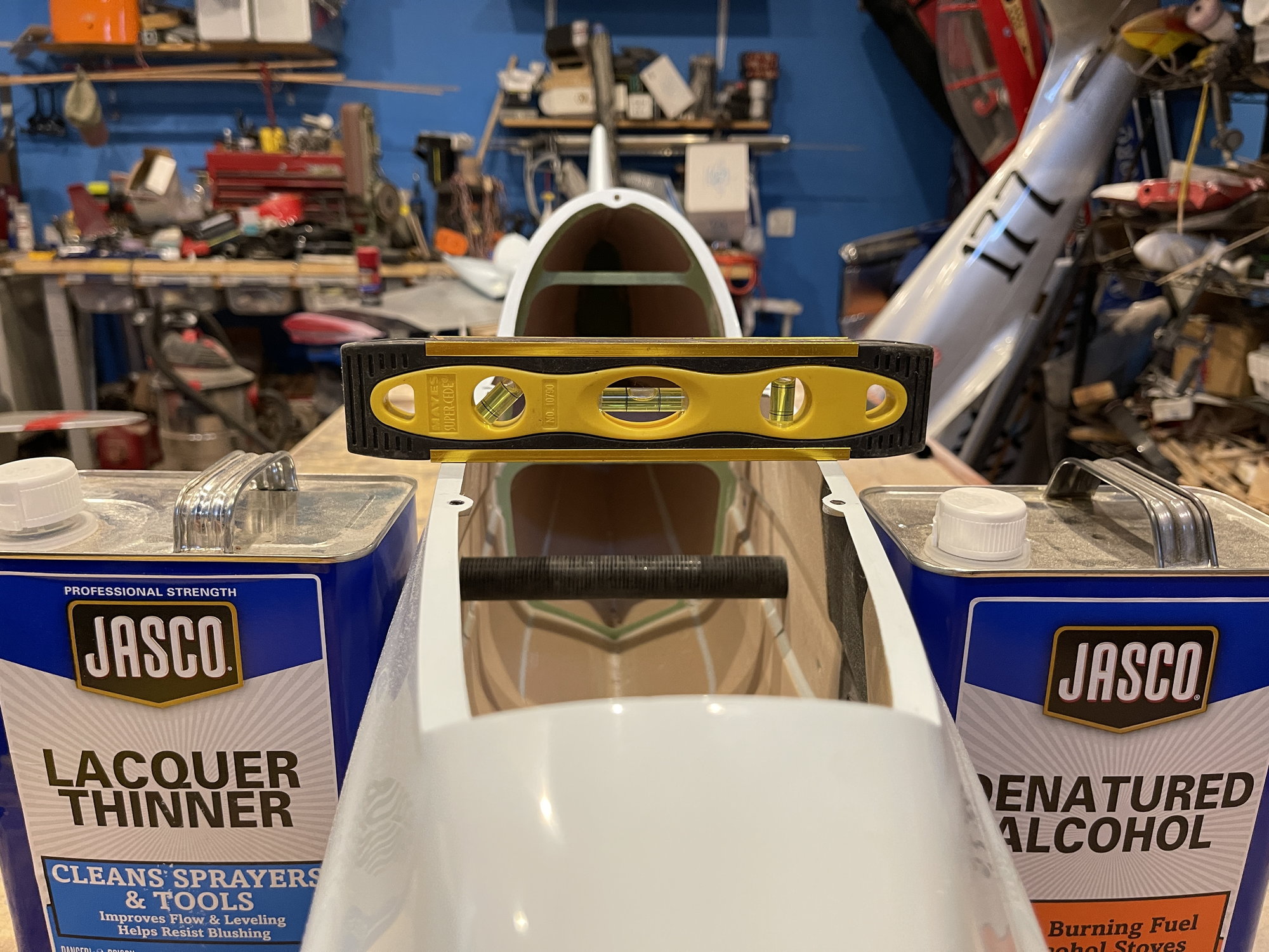
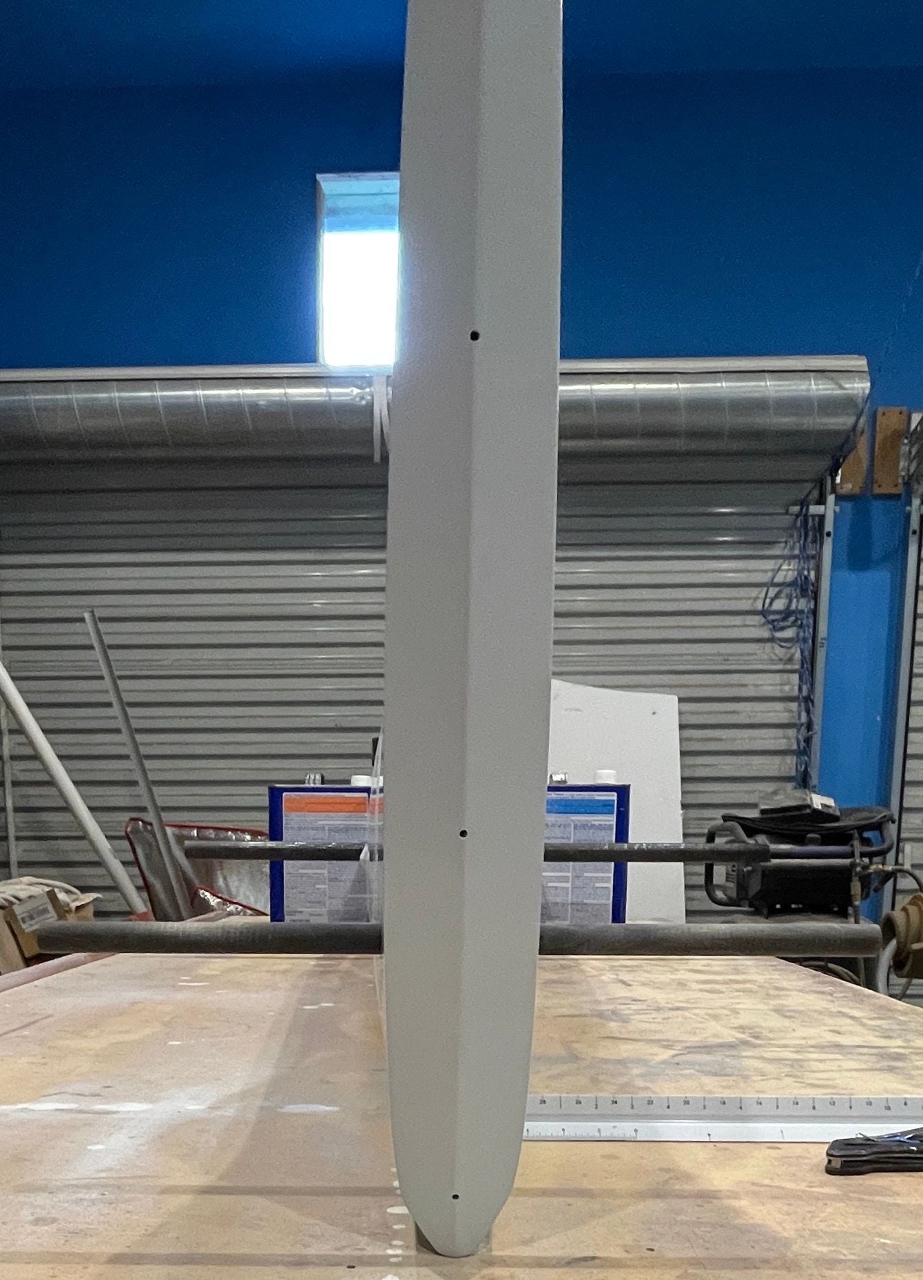
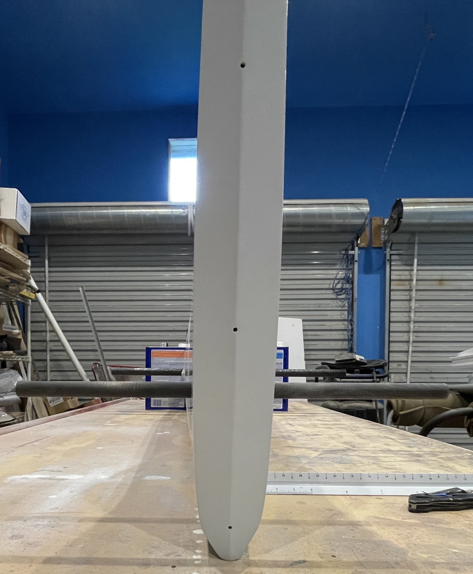
My original measurements reveals the wing tube was lower on the right side. SO with very little sanding of the fuselage side on the top of the right hole and bottom of the left hole, it is perfectly parallel to the stab tube and perfectly perpendicular to the vertical axis of the fin / tail end of the fuselage.
tail end. the stab tube is perpendicular to the trailing edge of the fin.
It is apparent, the wing tube is not. Right side lower than the left side.
the right side. take note of the lower black line on the 90 degree plastic triangle.
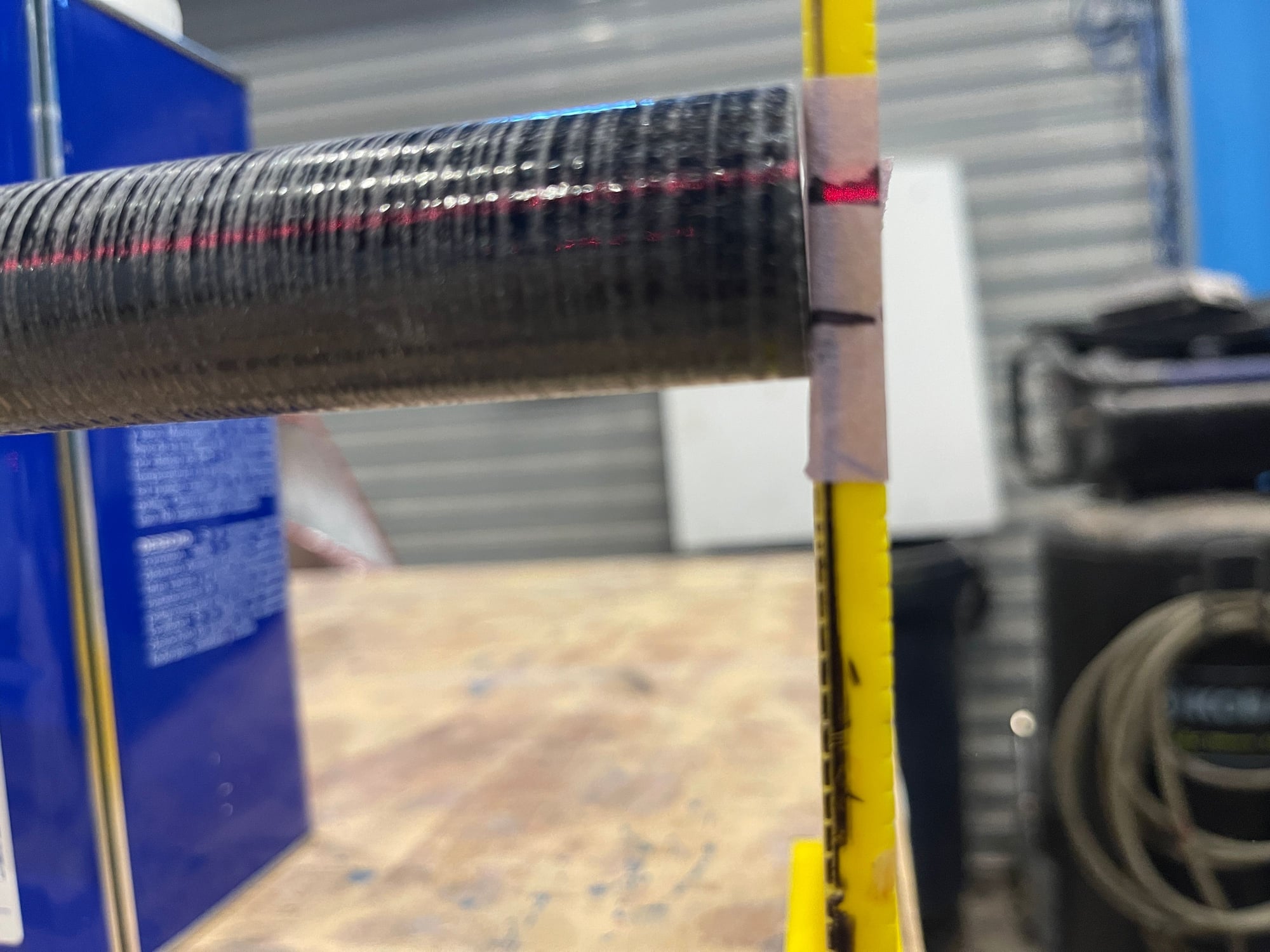
On the right side, the wing tube does not line up with the left side. it is lower.
tail end. the stab tube is perpendicular to the trailing edge of the fin.
It is apparent, the wing tube is not. Right side lower than the left side.
the right side. take note of the lower black line on the 90 degree plastic triangle.
On the right side, the wing tube does not line up with the left side. it is lower.
05-14-2022, 05:40 PM
#10
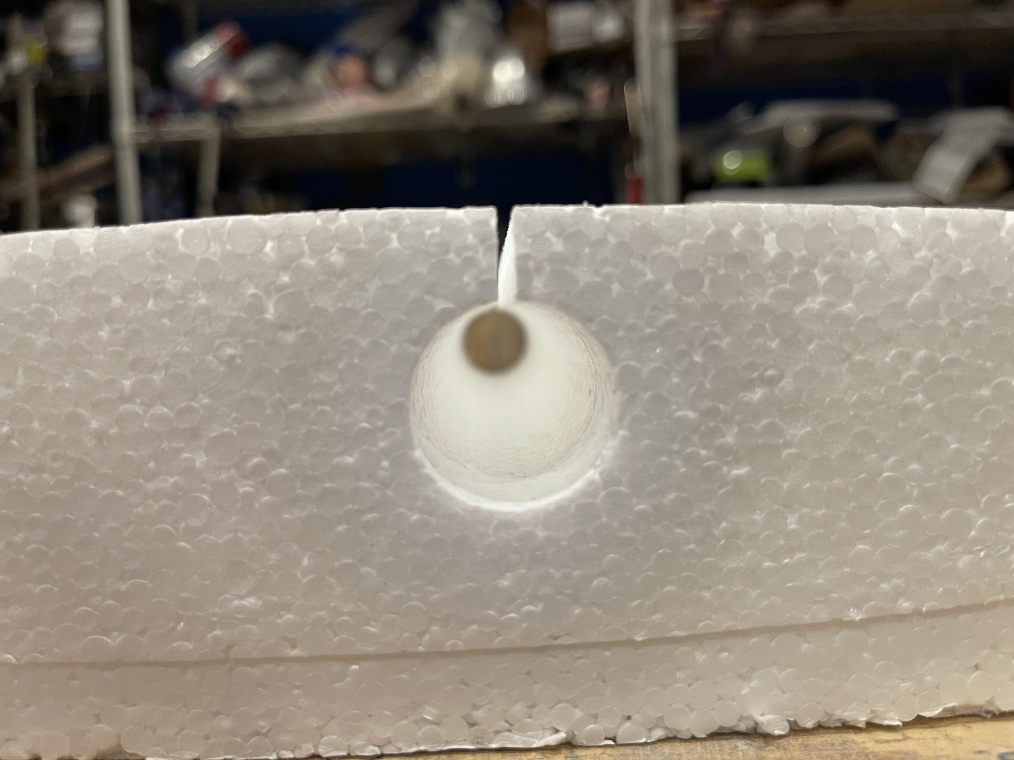
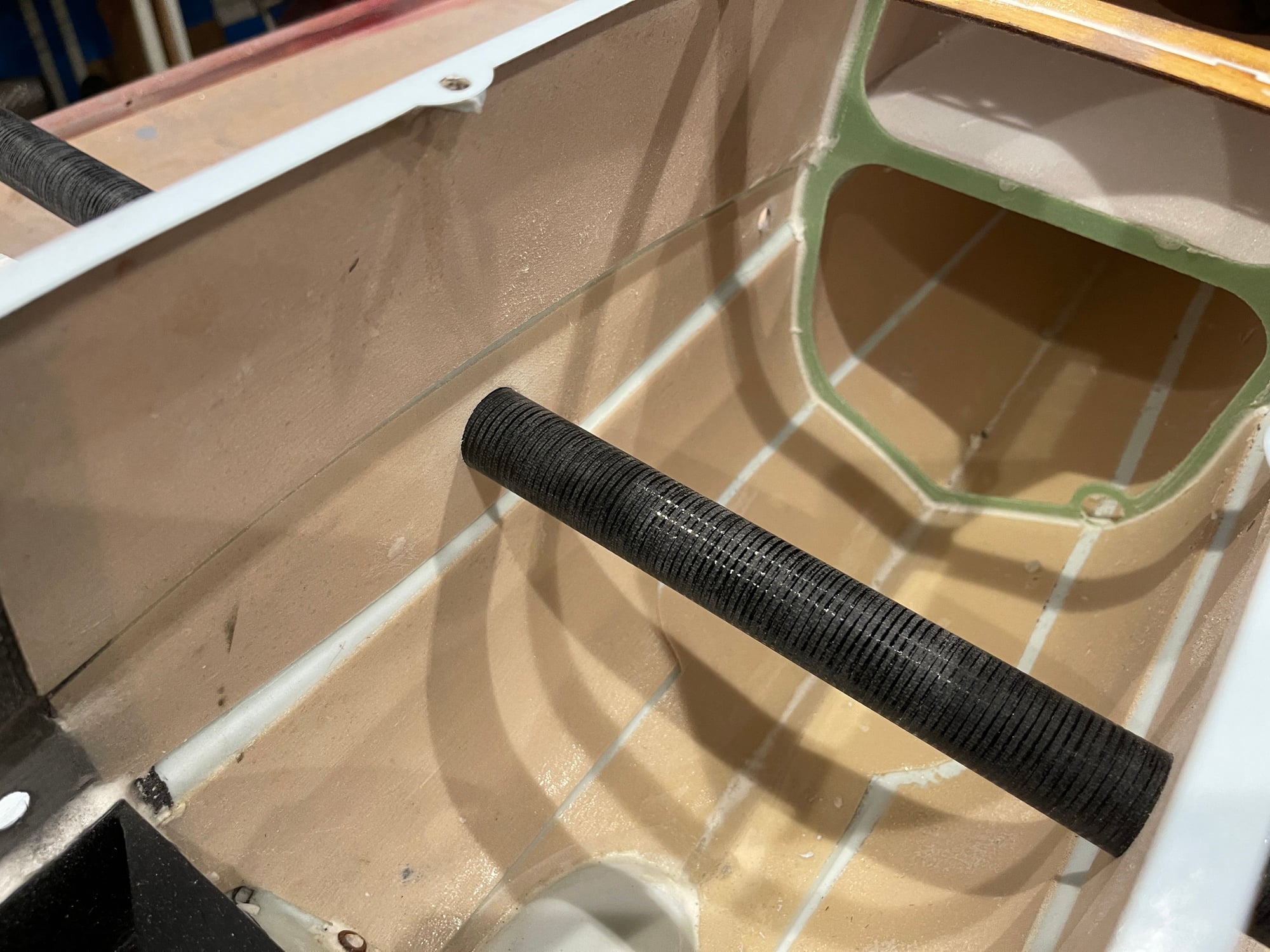
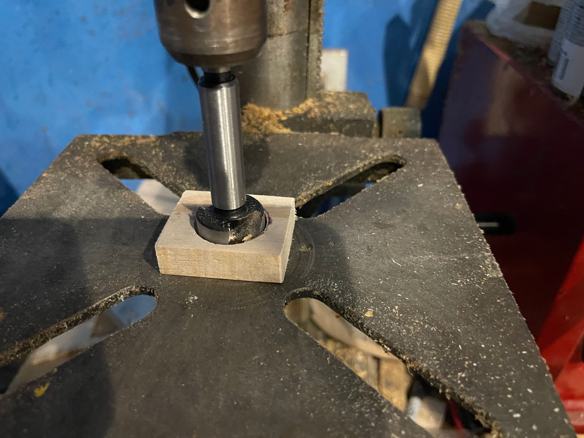
the balsa end of wing tube pheolic support blocks. Using the 1" forstner bit, it made a perfect hole.
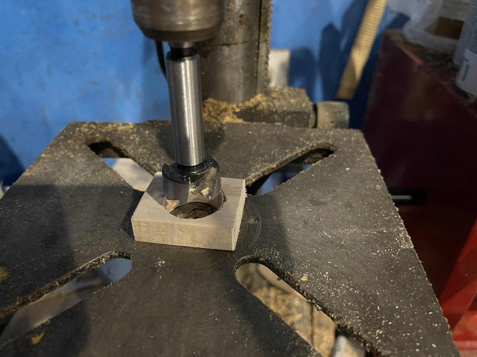
1" Forstner bit
I then capped the phenolic tube with 1/16th balsa. two pieces, at 90 degrees to each other, then sanded them down and flush with the phenolic tube sides.
wing tube sockets
they were cut to length and then I test fit the balsa blocks into the phenolic 1st, before setting them in the wings

now, time to see if it aligns
next step is to glue these in.
I will be using polyurthene glue (gorilla glue).
But very sparingly.
Use the least amoung of glue as possible, but totally covering all the surfaces, and then wipe off excess. otherwise, it will make a huge mess.
ONce I do this, I will then glue on the phenolic tube to the fuselage using the provided plywood doublers and using epoxy glue with milled fiberglass.
and, by checking that the tube is square on.
1" Forstner bit
I then capped the phenolic tube with 1/16th balsa. two pieces, at 90 degrees to each other, then sanded them down and flush with the phenolic tube sides.
wing tube sockets
they were cut to length and then I test fit the balsa blocks into the phenolic 1st, before setting them in the wings
now, time to see if it aligns
next step is to glue these in.
I will be using polyurthene glue (gorilla glue).
But very sparingly.
Use the least amoung of glue as possible, but totally covering all the surfaces, and then wipe off excess. otherwise, it will make a huge mess.
ONce I do this, I will then glue on the phenolic tube to the fuselage using the provided plywood doublers and using epoxy glue with milled fiberglass.
and, by checking that the tube is square on.
05-14-2022, 06:26 PM
#11
First step, I placed masking tape on the bottom side of the wing, in the cut out for where the balsa support block will be. Then I placed wax paper between the wing and the bottom shuck.
next step, I misted water with a spray bottle onto the inside of the foam core and on the outside of the balsa blocks and the phenoilc tube. Then, whilst wearing gloves, I coated the surfaces with Gorilla Glue (POLY-U), then I wiped off the excess. then inserted the tubes into the sockets and assure they were fully seated and engaged into the balsa blocks.
then wiped off excess glue again.

I then applied tape on the top side and then wax paper. I placed the top shuck over it, then again, wiped off excess extruded glue/foam
then I placed the wing tube into both wings and placed both wings flat on the build table, then placed 20 pounds weight directly over the wing tubes in the wings.

I will check them tomorrow morning and see where I am at.
next step, I misted water with a spray bottle onto the inside of the foam core and on the outside of the balsa blocks and the phenoilc tube. Then, whilst wearing gloves, I coated the surfaces with Gorilla Glue (POLY-U), then I wiped off the excess. then inserted the tubes into the sockets and assure they were fully seated and engaged into the balsa blocks.
then wiped off excess glue again.
I then applied tape on the top side and then wax paper. I placed the top shuck over it, then again, wiped off excess extruded glue/foam
then I placed the wing tube into both wings and placed both wings flat on the build table, then placed 20 pounds weight directly over the wing tubes in the wings.
I will check them tomorrow morning and see where I am at.
05-15-2022, 06:25 AM
#12
the wings came out good.
i did a test fitting of the wings on the fusleage, and noticed, the wing roots were not flush with the fusleage sides
SO i then did more measurements, I then adjusted the fuselage holes for the wing tube, slowly and carefully and frequently doing repeat measurements til i was pretty much square. then I glued in the phenolic tube into the fuselage.
I used 30 minute epoxy with the milled fiberglass, and again, went back and forth, to make sure the tube was square on in the two planes, parallel to the stab tube, and from the top view, looking down on the fuselage.
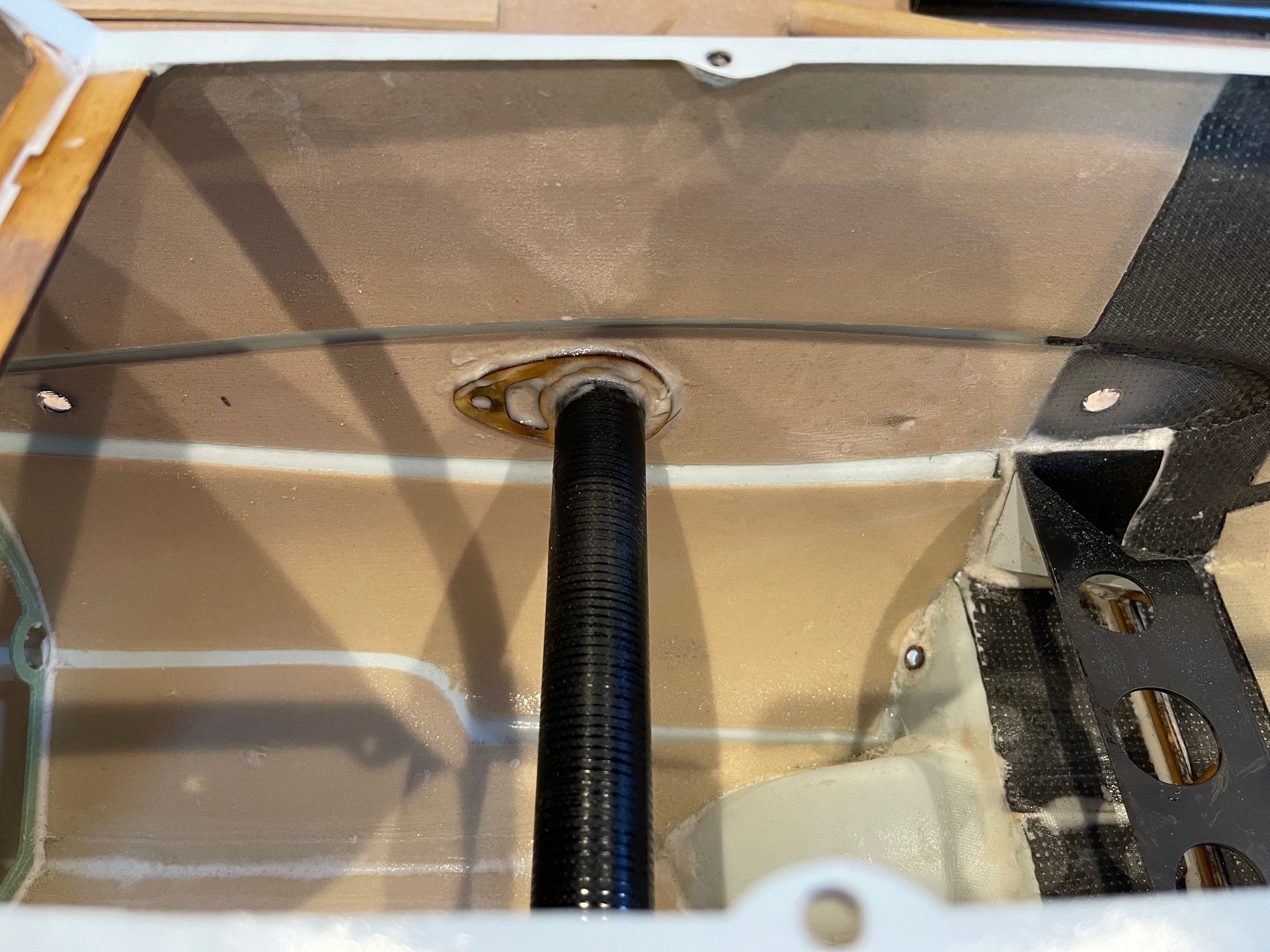
this is after sandind it down and flush.
next step, is to obtain 1/8" light ply and make the wing root caps and the stab root caps
i did a test fitting of the wings on the fusleage, and noticed, the wing roots were not flush with the fusleage sides
SO i then did more measurements, I then adjusted the fuselage holes for the wing tube, slowly and carefully and frequently doing repeat measurements til i was pretty much square. then I glued in the phenolic tube into the fuselage.
I used 30 minute epoxy with the milled fiberglass, and again, went back and forth, to make sure the tube was square on in the two planes, parallel to the stab tube, and from the top view, looking down on the fuselage.
this is after sandind it down and flush.
next step, is to obtain 1/8" light ply and make the wing root caps and the stab root caps
05-15-2022, 08:34 AM
#13
these are, what I call, the 1st draft version of the root caps.
What i will do:
1. finish preparing the wings and the stab foams: cut out servo box area, cut out foam to glue in the servo blocks, make the tunnel for the servo wire
2. on both wings and stabs, without root caps, i will install one surface at a time, and from the opposite side, use a long drill bit, and perforate the foam of the root, so for the wing, there will be 2 anti-rotation pins and one fastener. Once the perforation is done, I will remove the surface, and core out the foam such that I can glue in a hard point for the anti-rotation pin or the fastener. in the case of the stab, it will be for the anti-rotation pin that is adjustable. WIll show trhat later as to how I will do that.
3. then I will glue the cap on the root then sand it flush with the surface of the foam all the way around, that way, when I glue the skins onto the foam cores, they will capture the root ply. SHould make it tougher!
05-15-2022, 12:48 PM
#14
on the bottom of both wings, I cut out the foam for the servo.
I obtained some dimensions for the servos:
the Aileron and Rudder Servo should be:
Length 40 mm
Width 20 mm
Height 35 mm
The elevator servos should have the following dimensions:
Length 33 mm
Width 15 mm
Height 27 mm
Once I knew these measurements, they did agree with the marked out sizes on the foam.
Cutting out the foam. I used a knife, followed by the dremel with a cage.
Trial fitting a very similar sized servo
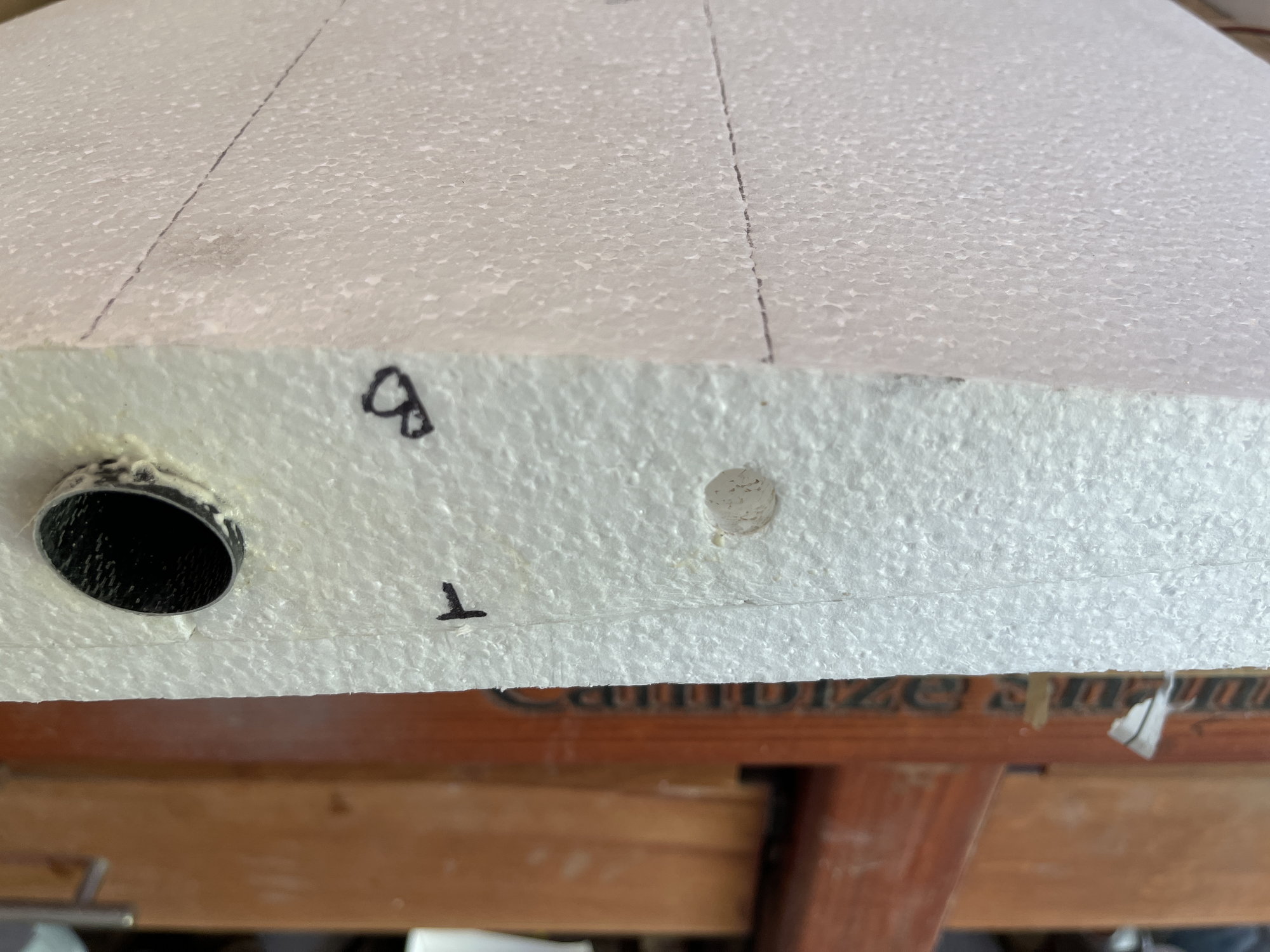
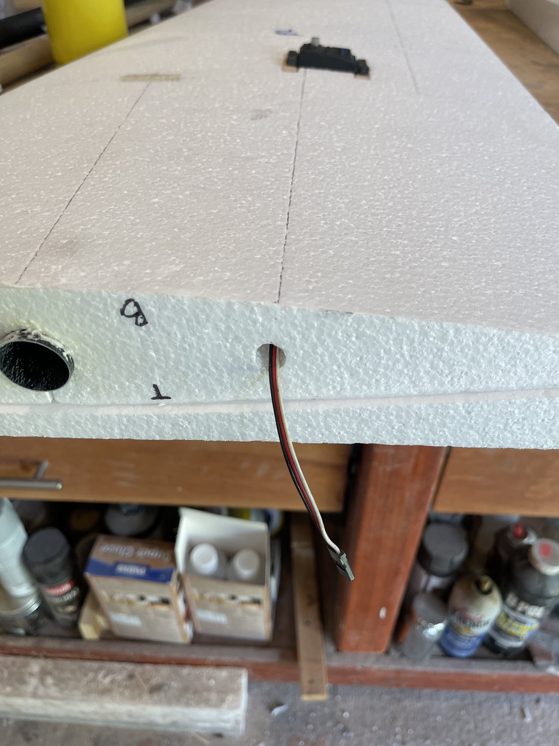
Making the tunnel for the servo lead / wire
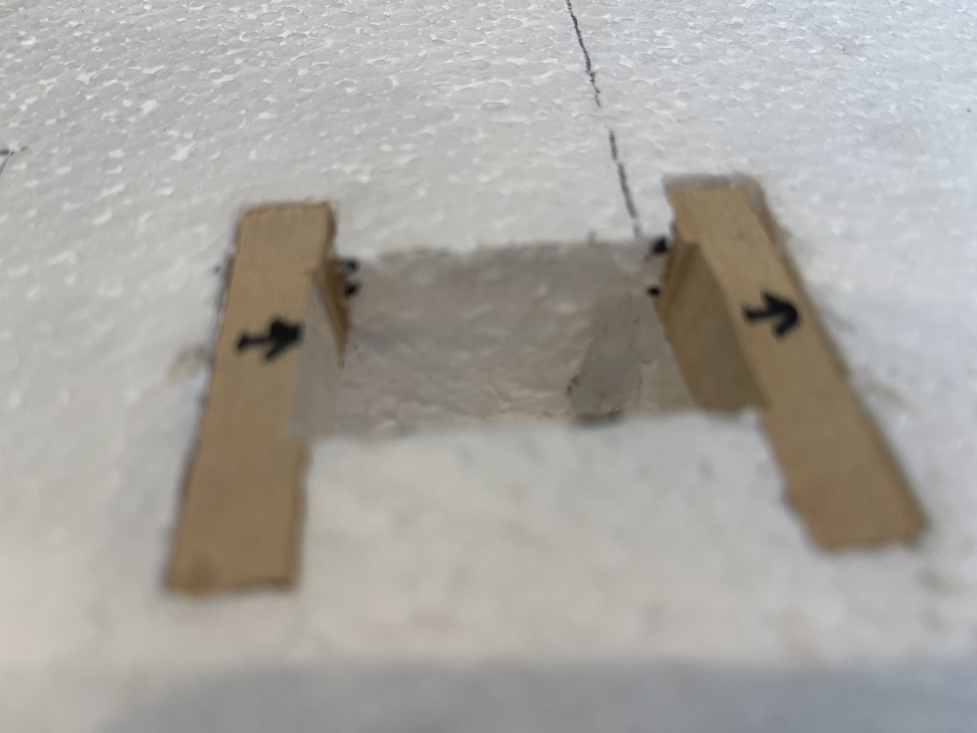
installing and gluing the servo mounts
servo trial fitting
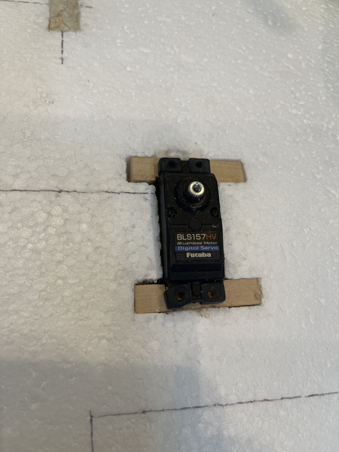
servo fits snug. THe balsa sheeting will cover this.
i did remove some wood from the hard spots for the servo mounts using a forstner bit, to lighten them up some.
I obtained some dimensions for the servos:
the Aileron and Rudder Servo should be:
Length 40 mm
Width 20 mm
Height 35 mm
The elevator servos should have the following dimensions:
Length 33 mm
Width 15 mm
Height 27 mm
Once I knew these measurements, they did agree with the marked out sizes on the foam.
Cutting out the foam. I used a knife, followed by the dremel with a cage.
Trial fitting a very similar sized servo
Making the tunnel for the servo lead / wire
installing and gluing the servo mounts
servo trial fitting
servo fits snug. THe balsa sheeting will cover this.
i did remove some wood from the hard spots for the servo mounts using a forstner bit, to lighten them up some.
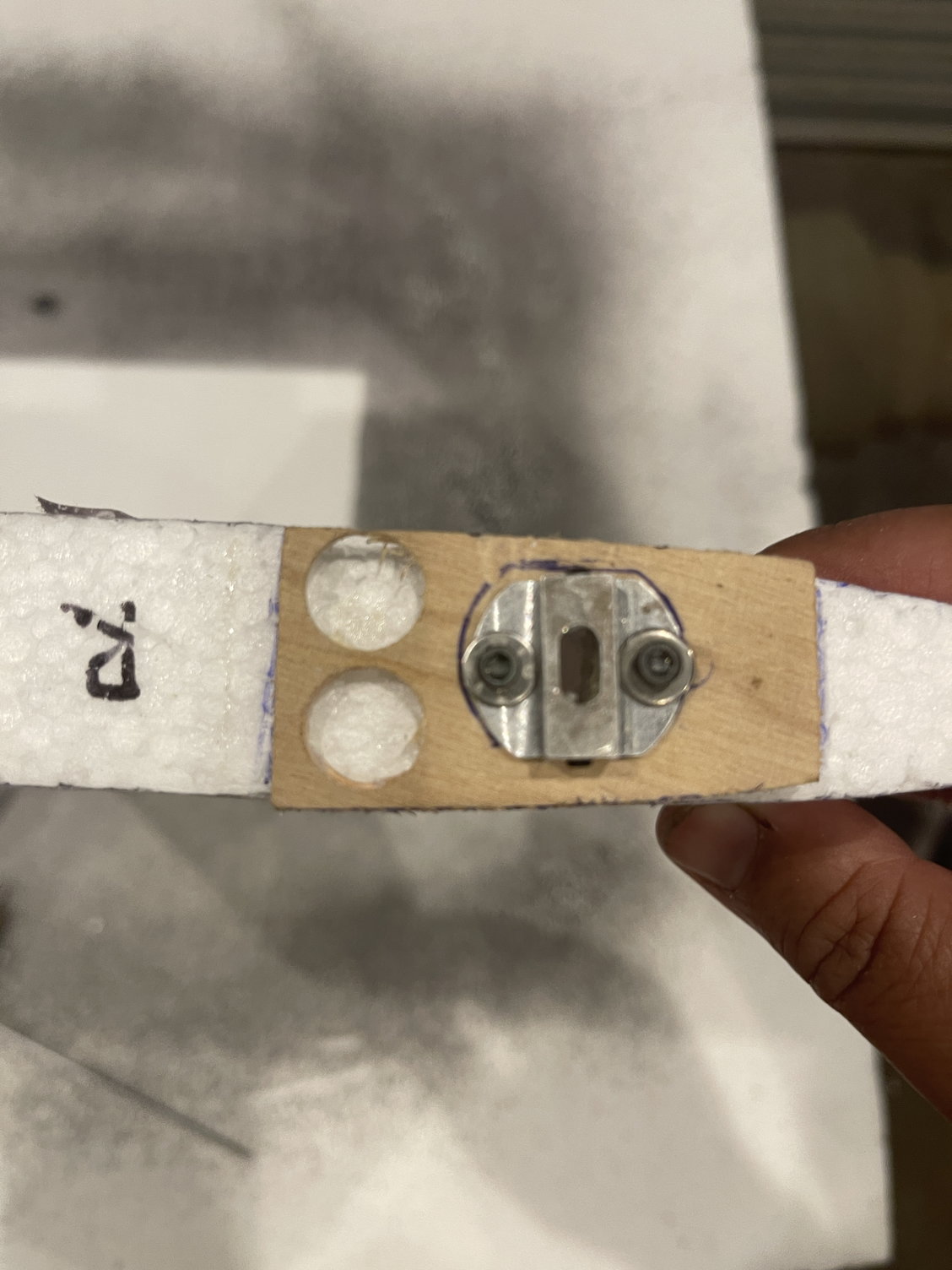
05-15-2022, 12:54 PM
#15
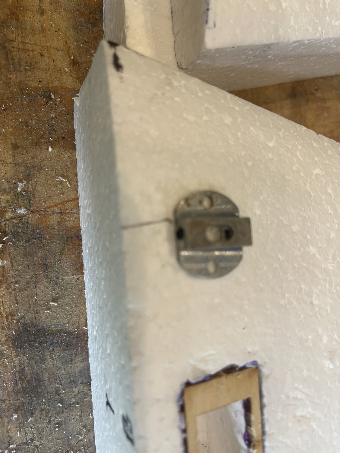
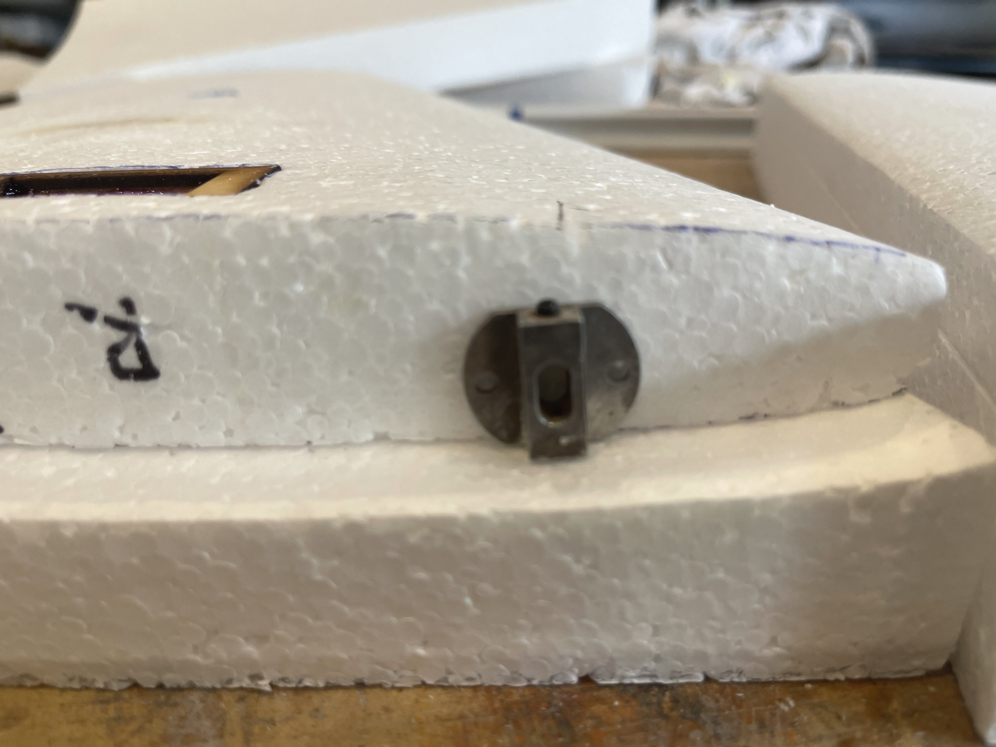
the kit comes with these 4 wing adjusters. I will definitely be installing these.
first step was to sand down the small laser cut tabs off them.
then, I obtained 1/4" thick plywood and made some mounts for the adjusters. I also installed the 4-40 inset threads.

first step was to sand down the small laser cut tabs off them.
then, I obtained 1/4" thick plywood and made some mounts for the adjusters. I also installed the 4-40 inset threads.
05-15-2022, 06:34 PM
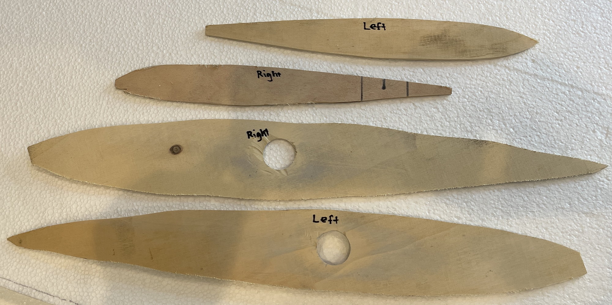
#16
just made these templates. One of the wing and one for the stab
this will assist me in finding the servo box and to cut out the surface.
stab templates
wing templates
next, I will make the template for the diamond pattern to be able to core out the wings and the stabs.
will do that tomorrow,
I have seen some examples on other ALLURE build threads, so I will do similar to those.
05-17-2022, 03:59 PM
#17
Was able to go early this morning and again just now to do a little bit more work,
Was able to install the phenolic into the stabs and also do a better job at finishing the root caps.

curing the phenolics into the foam of the stabs using polyurethane glue.
DOing some more sanding on the root caps.
the root caps are not glued on yet. I still need to make the cut out for the servo and make the servo lead tunnel.
I also am awaiting the aluminum stab adjustment gear.
Was able to install the phenolic into the stabs and also do a better job at finishing the root caps.
curing the phenolics into the foam of the stabs using polyurethane glue.
DOing some more sanding on the root caps.
the root caps are not glued on yet. I still need to make the cut out for the servo and make the servo lead tunnel.
I also am awaiting the aluminum stab adjustment gear.
05-18-2022, 06:21 PM
#19
Yes sir! SUre do hope so. If Bryan is not too busy, and he can help me by trimming the Proteus, then I will move up to INT. To me, makes no sense for me to fly Sportsman any longer! BUT the proteus needs a lot of help!
I will never do another biplane again.
I will never do another biplane again.
05-19-2022, 05:30 AM
#20
If you ever feel the need to thin the heard, I'll take the bipe. I miss my BiSide.

The following users liked this post:
orthobird (05-22-2022)
05-22-2022, 06:12 PM
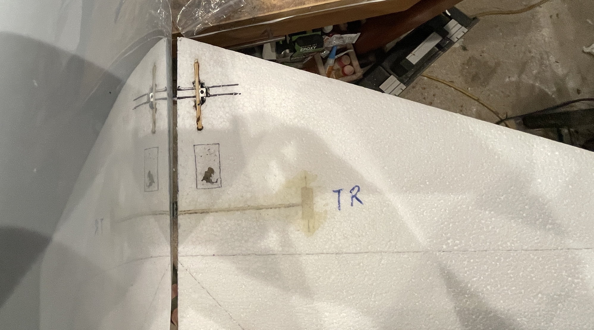
#21
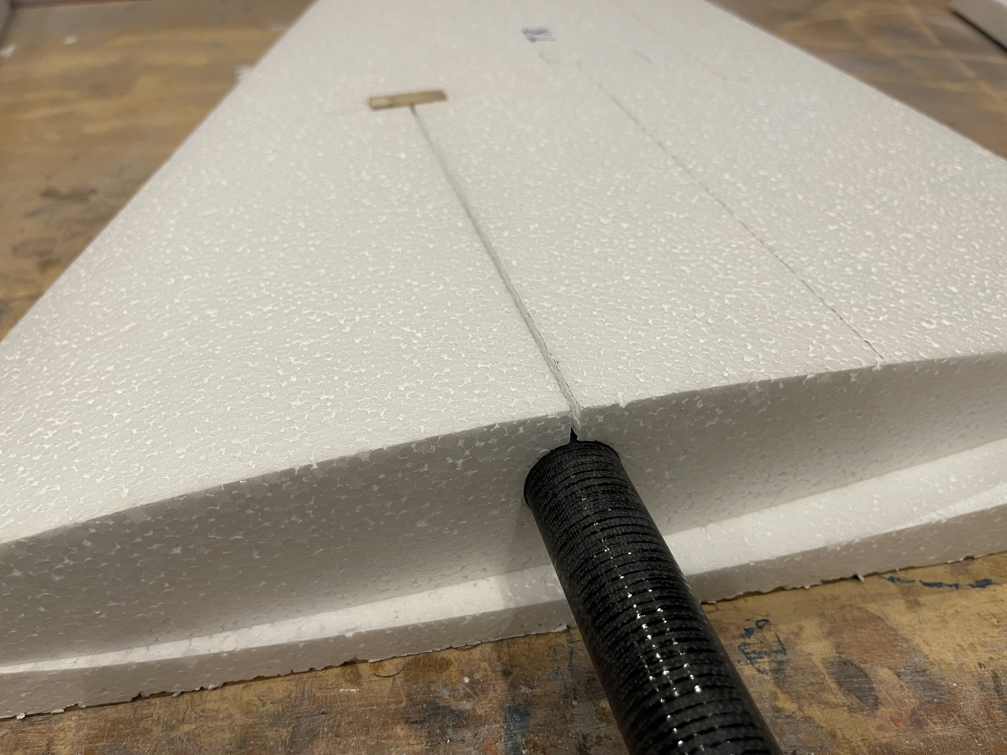
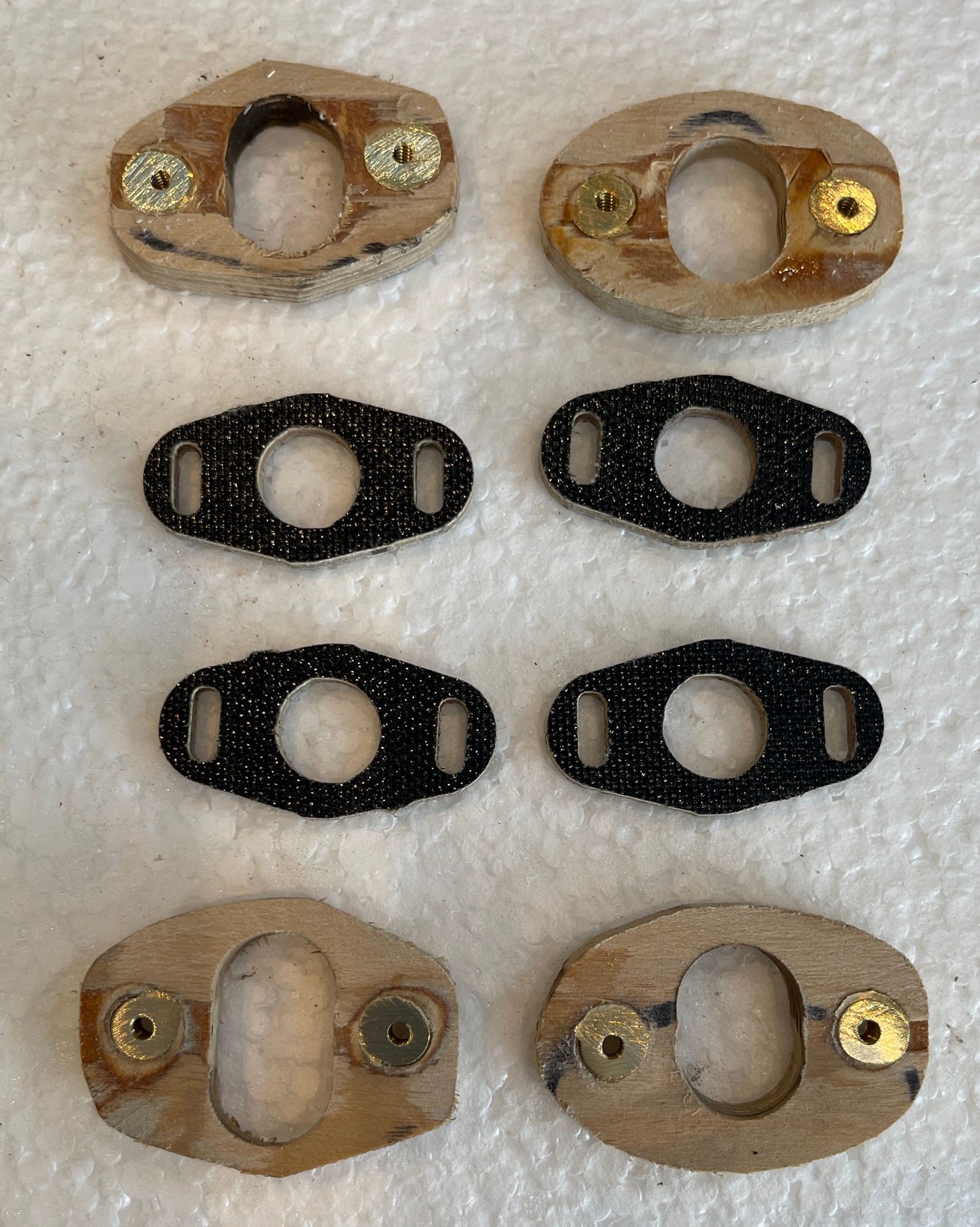
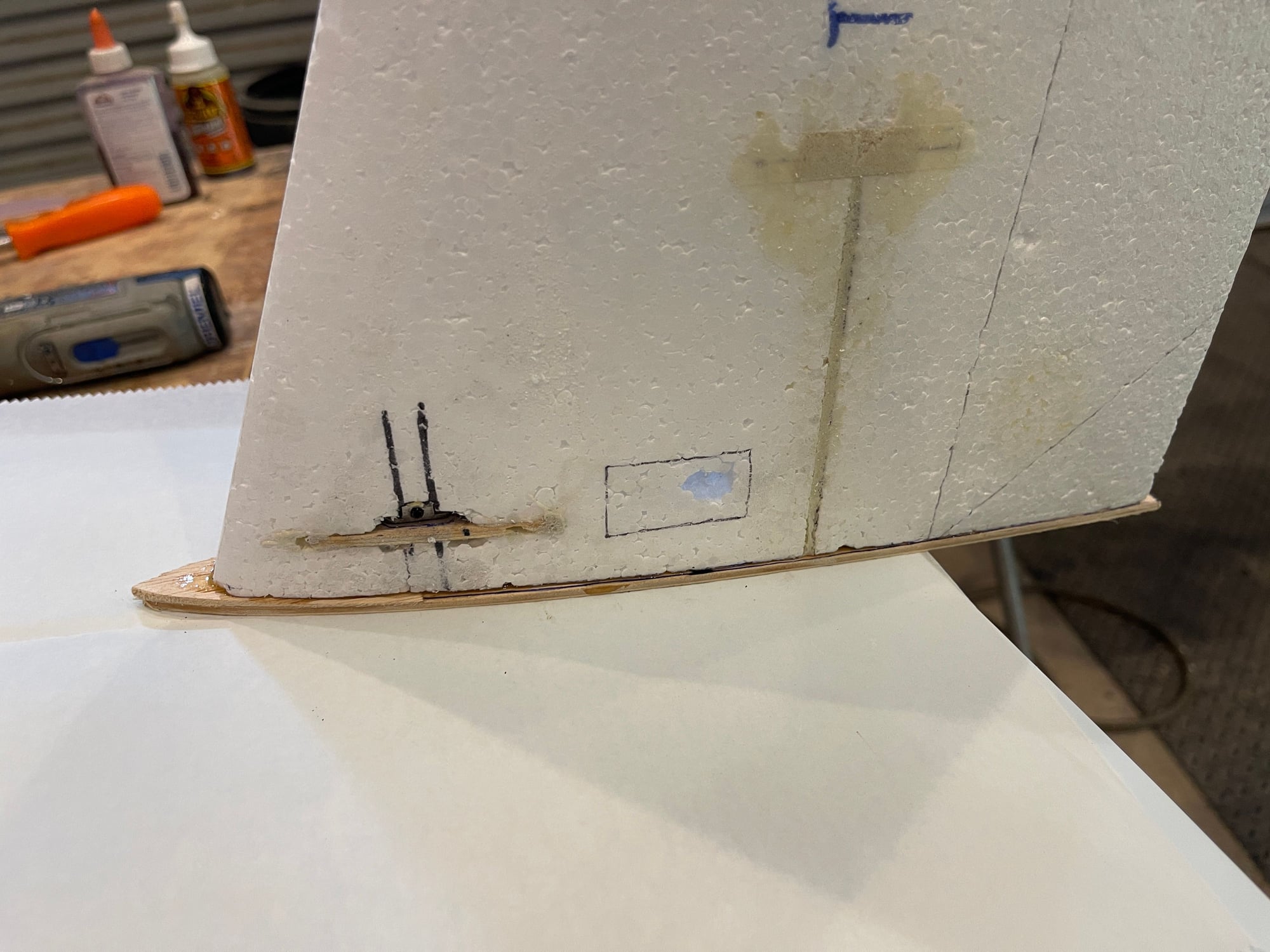
Installing the stab adjusters:
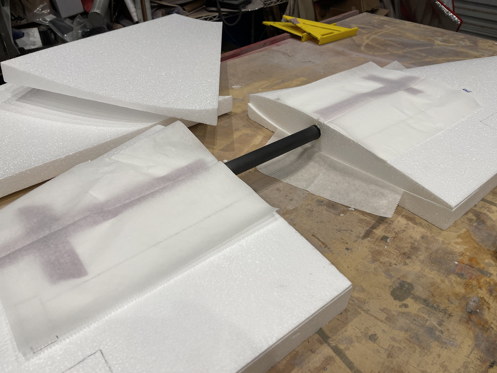
I placed the stab on, and from opposite side, I poked the foam with the CF rod. this gave me an idea on where the CF rod enters the stab root,
then, I had to know exactly the angle that the rod enters the stab, and this is not at a right angle to the root.
Once I dtermined this, then I drew a line from front to back, of where I was to remove a 1/8" thick sliver of foam so that the light ply mount for the adjuster will go.
Pictures explain best.
When the time comes to glue it all in, I did so, with the stab installed and rod in place, to hold the block such that it will not bind at the time of installing the stabs.
05-22-2022, 06:16 PM
#22
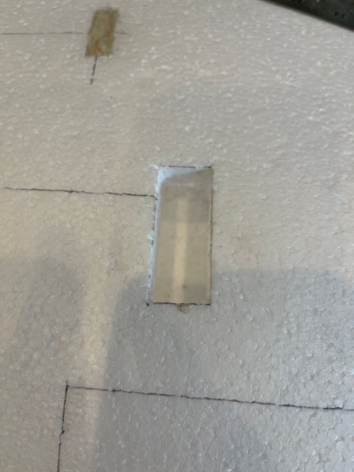
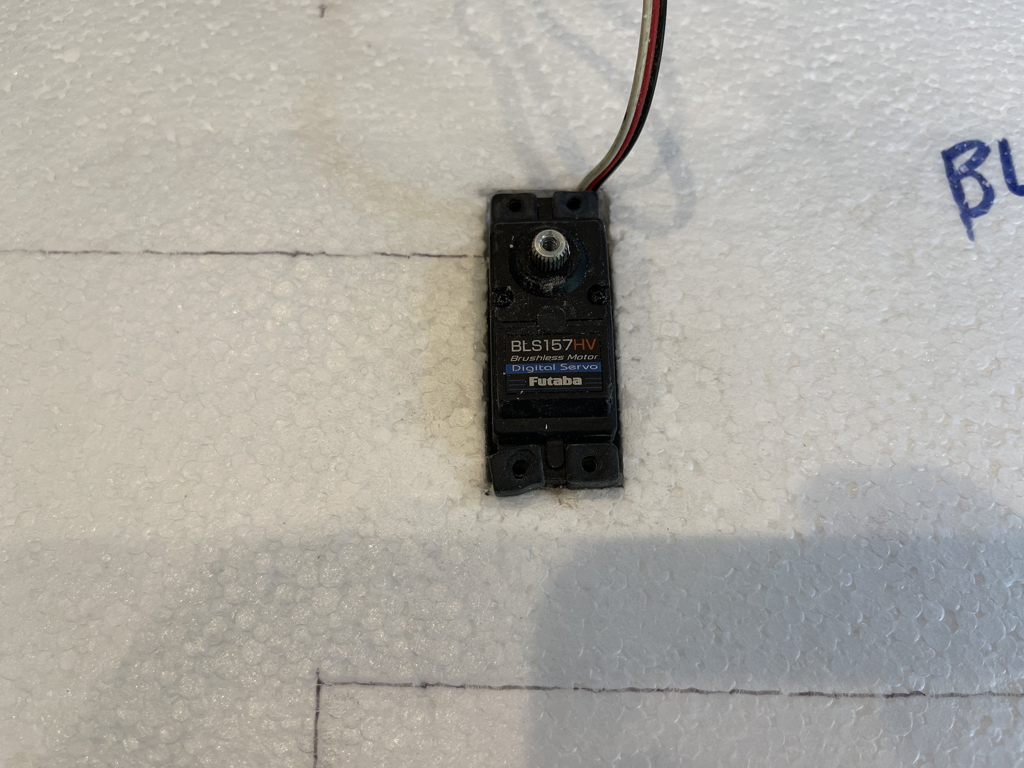
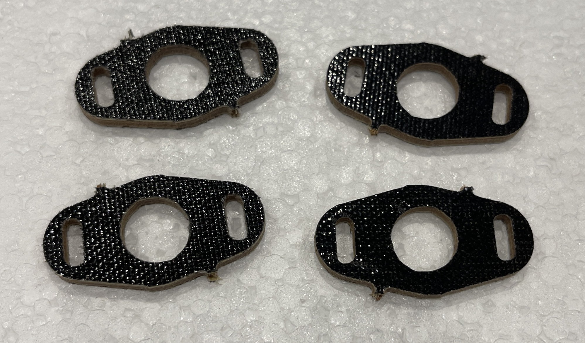
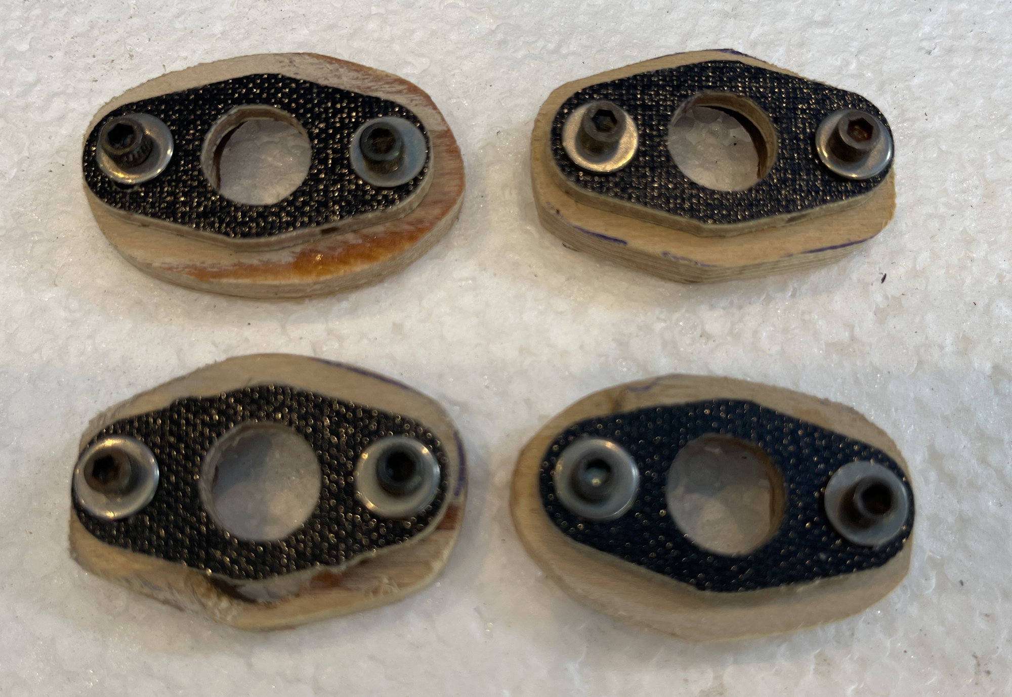
placement of hard point for the surface control horn:
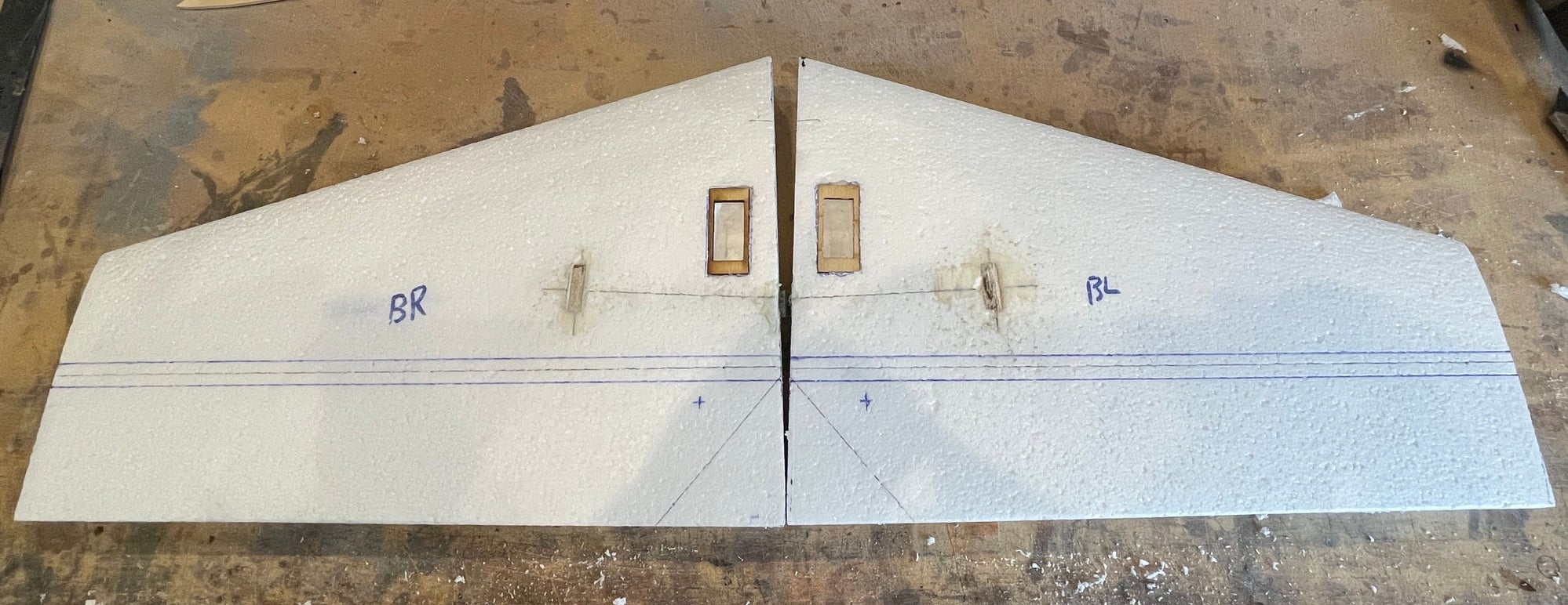
the servo mounts installed and glued in.
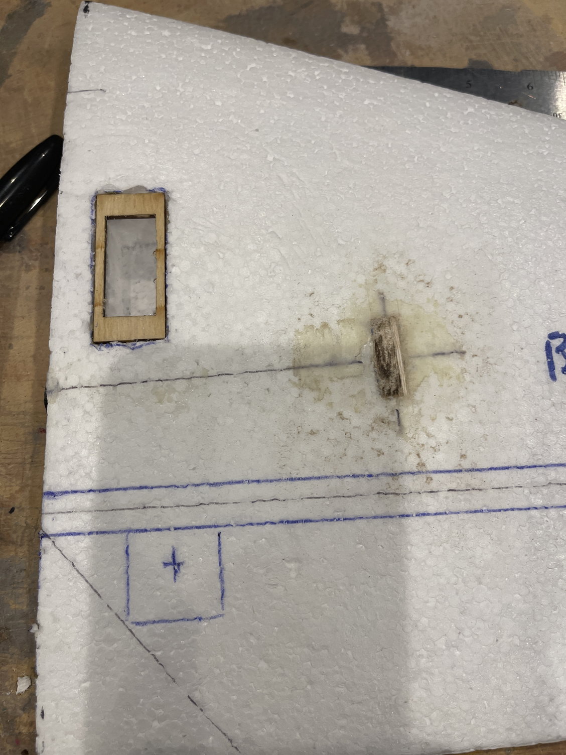
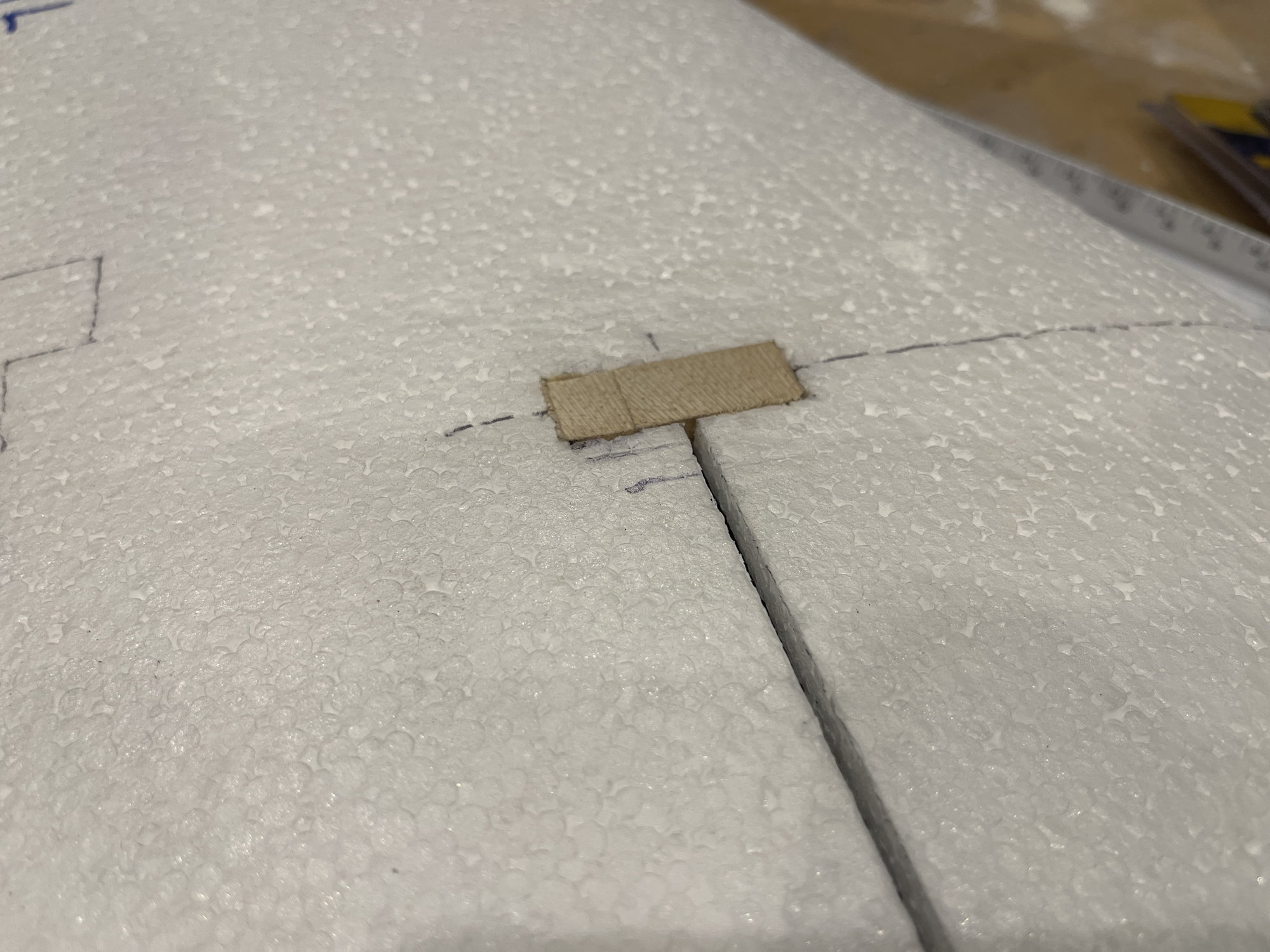
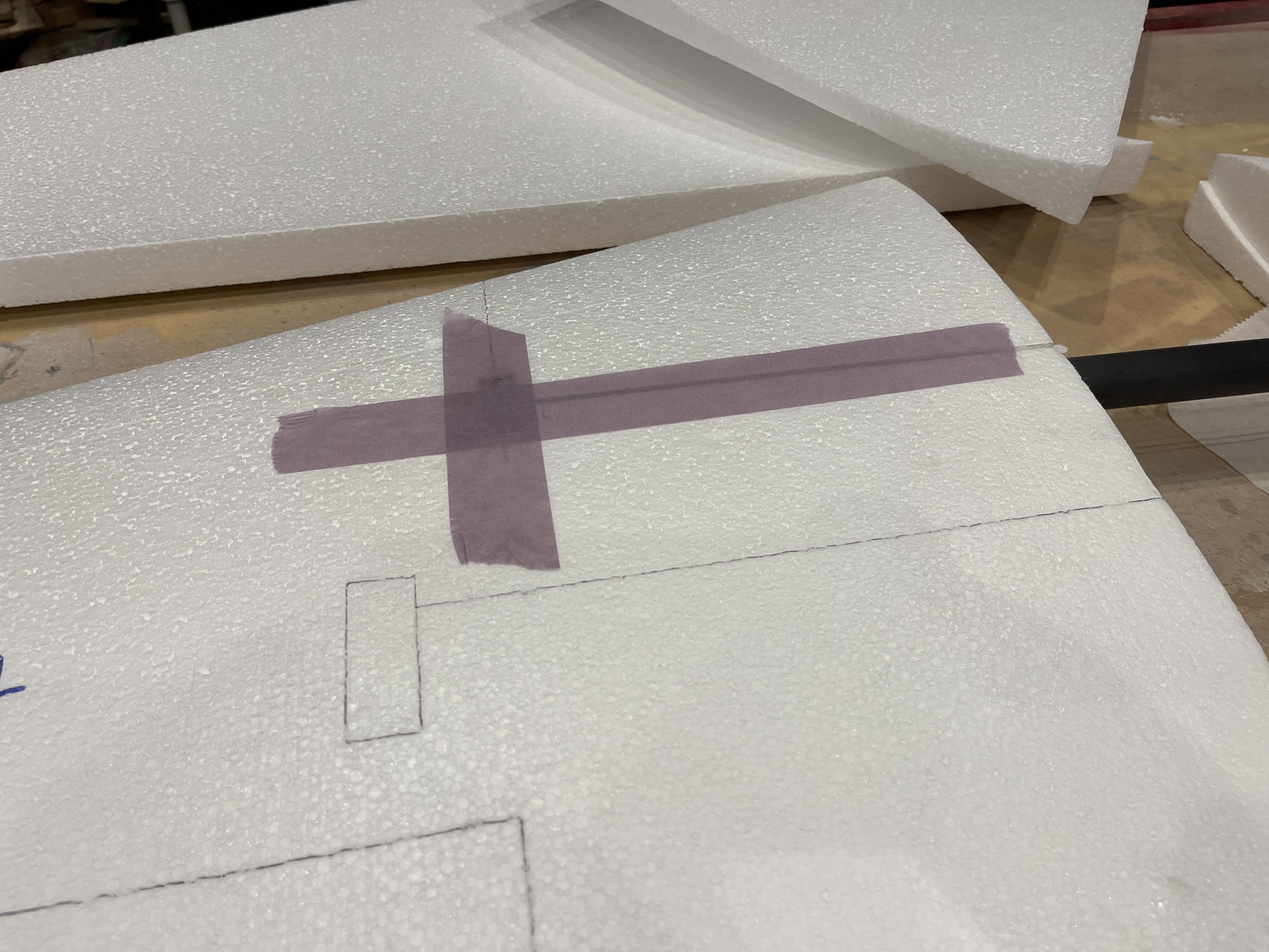
I drew a line forward and aft to hinge line that depitcs the foam that will be cut out to replace with the LE and TE, which will be 1/4" wide.
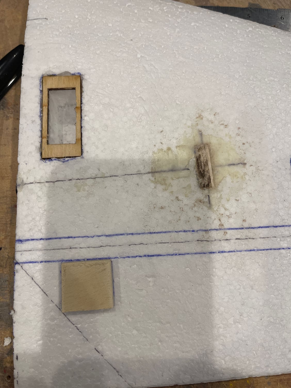
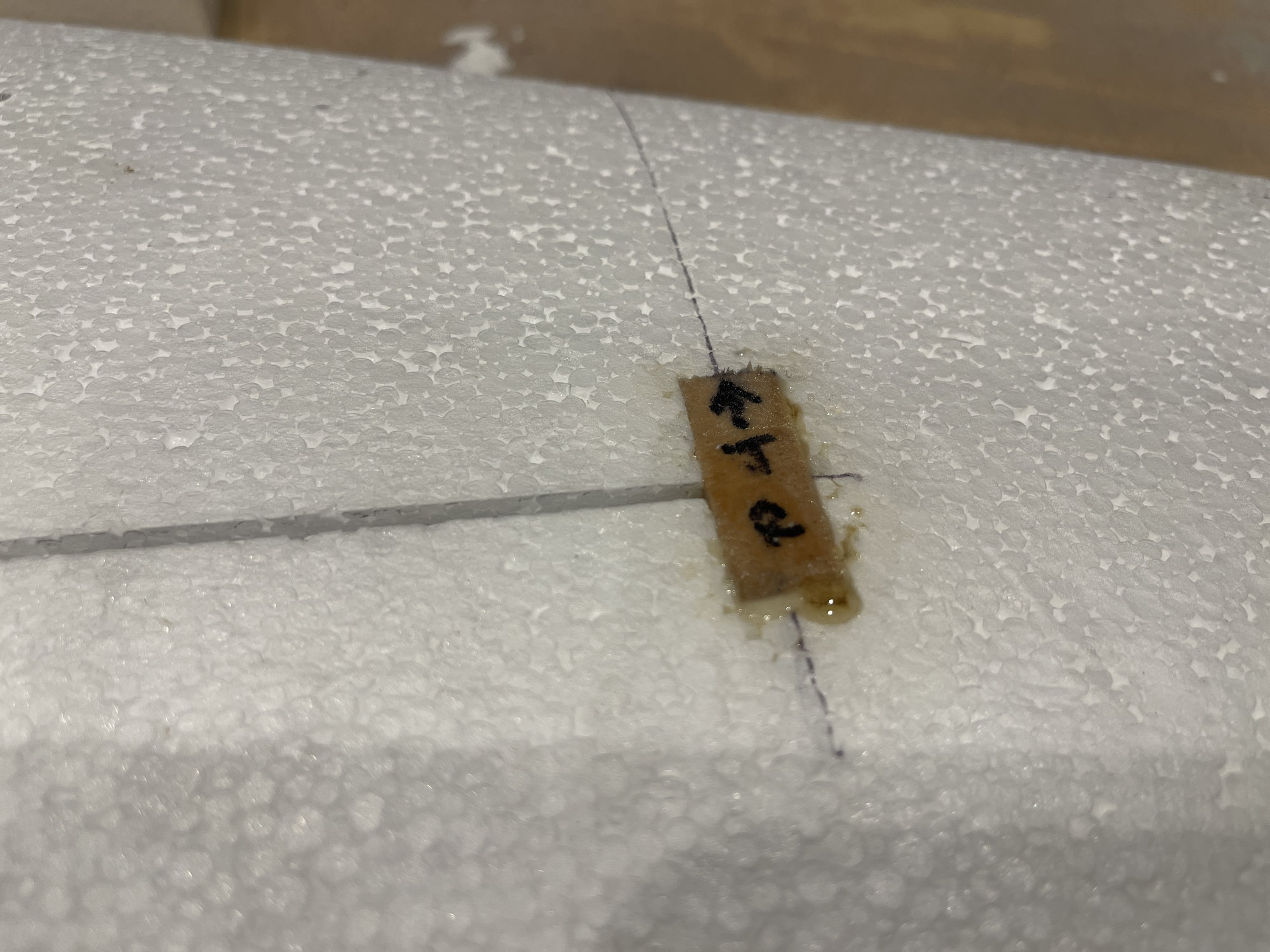
hard point location. this is light ply laminate. Weighs 2 grams.
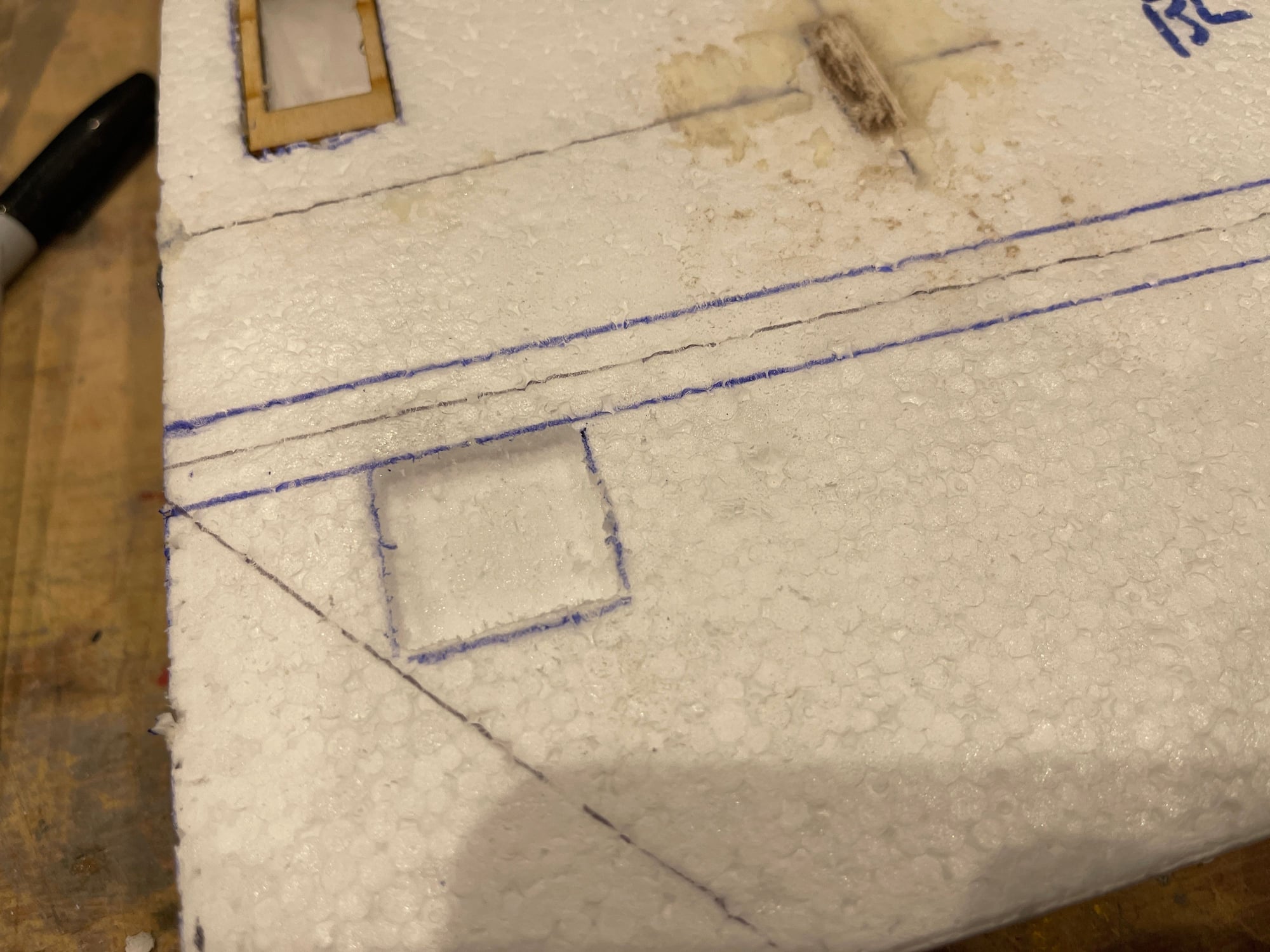
after cut out with Dremel.
the servo mounts installed and glued in.
I drew a line forward and aft to hinge line that depitcs the foam that will be cut out to replace with the LE and TE, which will be 1/4" wide.
hard point location. this is light ply laminate. Weighs 2 grams.
after cut out with Dremel.
05-22-2022, 06:23 PM
#23
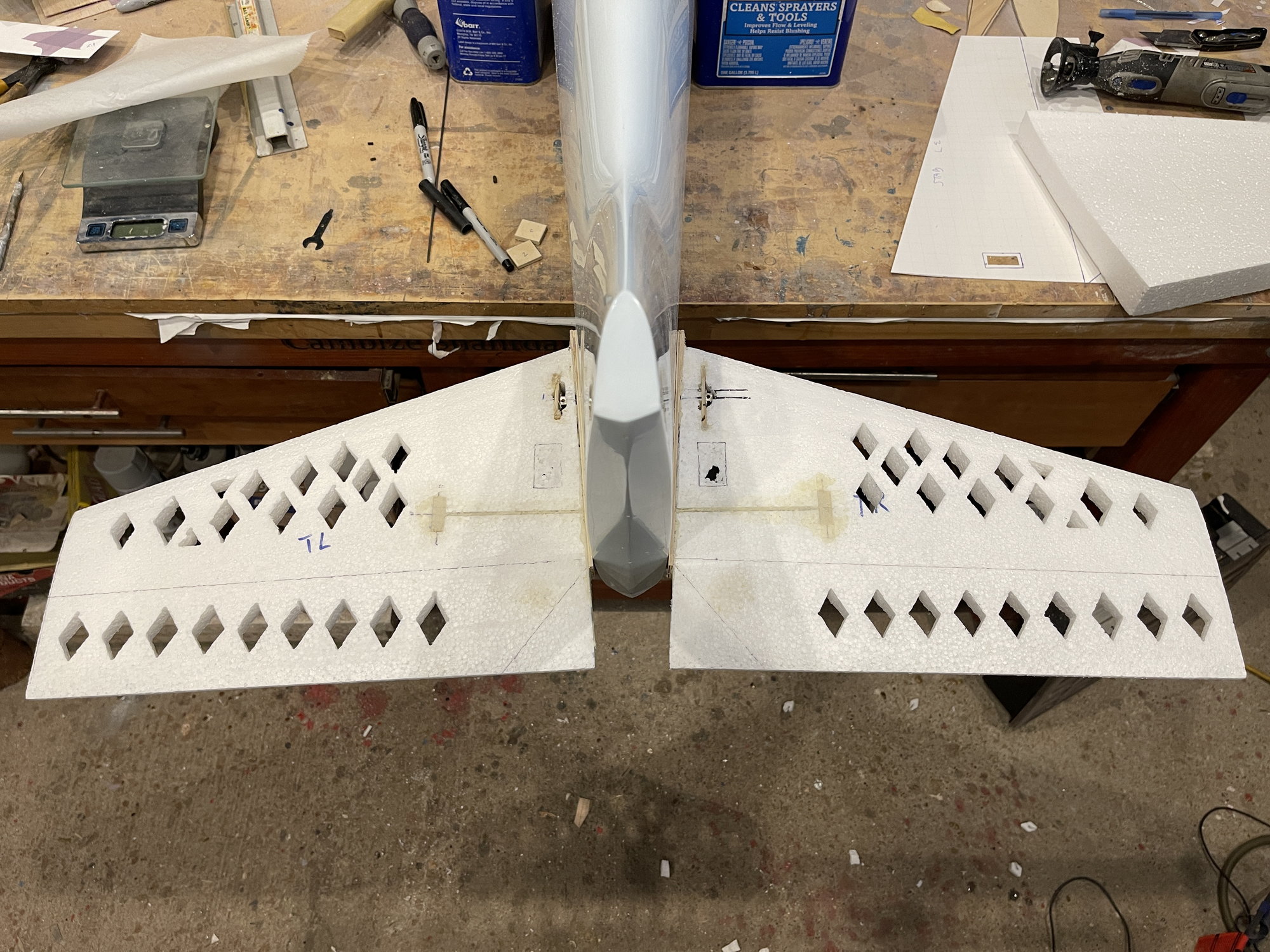
SO far, the stab weight, no servo, not covered, not finished. It is at 90 grams.
Based on Jason Arnold's build thread of his ALlure, his stab which was built up and sheeted, had a weighs of 90 grams prior to servo and control linkage installation.,
So this kind of gives me an idea on a goal.

Based on Jason Arnold's build thread of his ALlure, his stab which was built up and sheeted, had a weighs of 90 grams prior to servo and control linkage installation.,
So this kind of gives me an idea on a goal.
05-23-2022, 03:09 PM
#25
Thank you Ricardo.
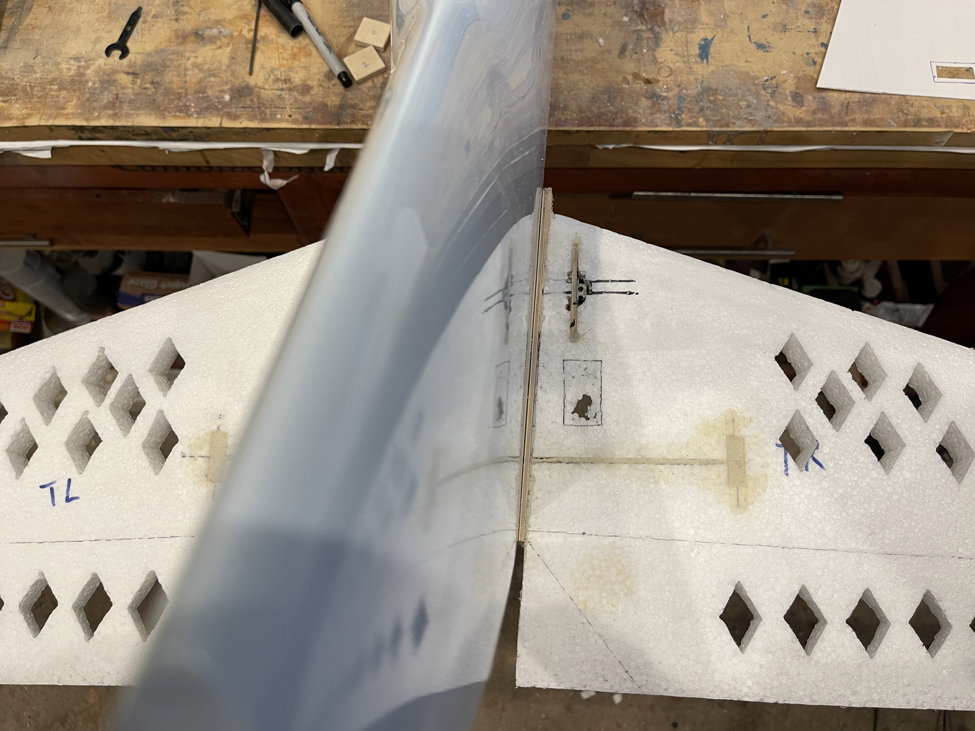
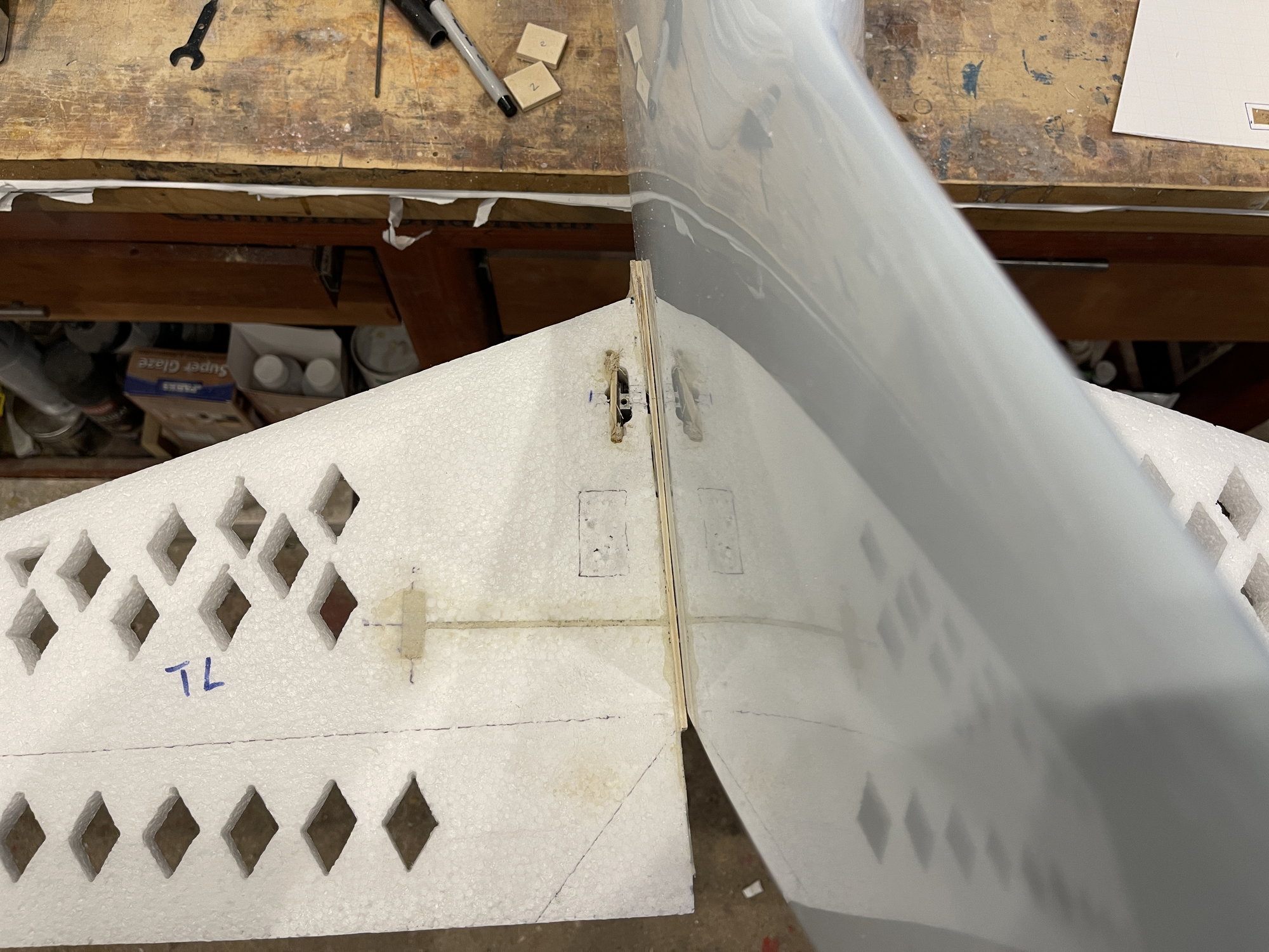
I did glue the stan root caps to the stab foam. I like to do one at a time, and i will shim them, such that, the root cap sits nice and snug against the fuselage side.
I place wax paper on fuselage side and then with the fuse on its side, I place the stab with root cap on.
the stabs are now ready to be sheeted.
Just some very small steps to do:
install a very small hard point for a screw to fix the stab tube to the stab and small balsa block with a hole over the adjuster area.
Once I do these, then I can glue the skins onto the stab foam cores.
I will do one at a time.
there is no race here.
I also did some weighing. I am imagining the goal is 130 grams per stab, with the stab finished, servo installed, ready to fly. and painted.
So far, the foam as you see is about 40 grams.
the skins are 50 grams, but this is untrimmed. will be less once I glue them on and set them aside.
Im still trying to decide on which glue to use? Poly U versus epoxy resin.
I do not like the poly-u glue becuase it starts to set up quickly. and the epoxy resin gives me plenty of time to work on it.
this is to demonstrate the contact of the root cap to the fuselage side.
The following 2 users liked this post by orthobird:
Ricardo M. (05-24-2022),
wattsup (05-24-2022)