


JW B³ker Jungmeister build
 11-14-2021, 02:39 AM
#1

The main reason I'm posting this build is because the first thing I did when I got the kit home was search for prior builds. Maybe they're out there but I sure couldn't find them. The only real resource was Jan's build - somewhere in Scandinavia - here: https://www.modelbouwforum.nl/thread...schaal.257895/ I used Google Translator to get a rough idea of what he was saying! I'm very grateful for his postings but sadly, he left out a lot of important detail. SO: I'm not going to cover anything you can't already find in his thread. Thanks Jan!! With that, let's get started.
Last edited by mitchilito; 11-14-2021 at 02:42 PM.

The following users liked this post:
Steve (05-12-2022)
11-14-2021, 03:19 AM
#2
Pluses:
Thoroughly modern CNC design and execution. The kit practically falls together and is a LOT of fun to build.
Fantastic wood quality. It isn't easy finding so much good wood without a lot of effort - ask me how I know!
Price is really reasonable for what you get, in my opinion.
Minuses
Instructions: I had to get the vendor, Vogelsang Aeroscale, to send me a translation of the instruction book. It's NOT a perfect translation. And then you are going to find that the instructions call out parts and features that are no longer in the design! This was a surprise. And if that wasn't bad enough the drawings don't agree with the parts supplied! Another big surprise, to say the least. These things would be pretty easy for JW to fix so I find it strange. I guess they cover their butts by saying right up front: "this kit is for expert builders etc." With that said, I would happily buy this kit again and slog my way through these difficulties. It's easily worth the trouble.
Wood: like I said, the wood in the box is just fantastic. However, there's simply not enough of it! All four wing panels and the top and bottom center sections all start with built up front and back spar assemblies and there is NOT enough material in the box to built them all (see edit below for an update). And the design depends on a lot of 3mm balsa sheeting and there is not even half of what is required in the kit! This I cannot understand. I had to outsource a lot of wood. But again, the price of this kit is still well worth this additional effort in my opinion.
Speaking of spar assemblies: the 1mm shear-webbing supplied for these assemblies is CNC routed to size in two BIG sheets. The problem is, on one of the sheets they were cut too tall which induces a LOT of work to correct. This is another thing that would be so easy for JW to fix. You will see what I did to correct this problem (fortunately I have a machine shop at my disposal. I hate to think about what it would've taken otherwise).
NOTE: I'm only half done with the build as I write this so I will probably revisit this post as I go
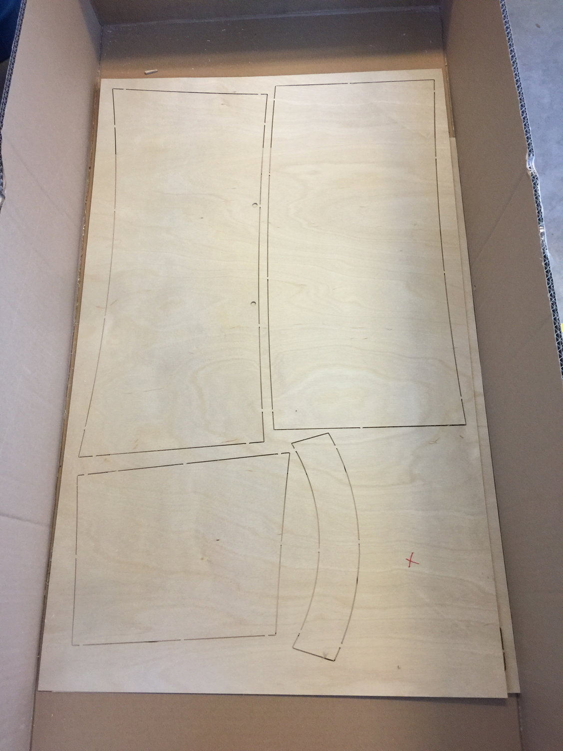
EDIT #1: turns out there WAS enough shear webbing for all the spars. I finally pulled out all the fuselage parts sheets to mark and inventory and on the very bottom of the kit box there were several large sheets of .8mm plywood parts for fuselage. This is the same material the sheer webs are made of so I looked close and sure enough there is a spot where it appears there is enough scrap to make the last center section spar (even the grain is in the proper direction). Look for the red x in this pic:
Thoroughly modern CNC design and execution. The kit practically falls together and is a LOT of fun to build.
Fantastic wood quality. It isn't easy finding so much good wood without a lot of effort - ask me how I know!
Price is really reasonable for what you get, in my opinion.
Minuses
Instructions: I had to get the vendor, Vogelsang Aeroscale, to send me a translation of the instruction book. It's NOT a perfect translation. And then you are going to find that the instructions call out parts and features that are no longer in the design! This was a surprise. And if that wasn't bad enough the drawings don't agree with the parts supplied! Another big surprise, to say the least. These things would be pretty easy for JW to fix so I find it strange. I guess they cover their butts by saying right up front: "this kit is for expert builders etc." With that said, I would happily buy this kit again and slog my way through these difficulties. It's easily worth the trouble.
Wood: like I said, the wood in the box is just fantastic. However, there's simply not enough of it! All four wing panels and the top and bottom center sections all start with built up front and back spar assemblies and there is NOT enough material in the box to built them all (see edit below for an update). And the design depends on a lot of 3mm balsa sheeting and there is not even half of what is required in the kit! This I cannot understand. I had to outsource a lot of wood. But again, the price of this kit is still well worth this additional effort in my opinion.
Speaking of spar assemblies: the 1mm shear-webbing supplied for these assemblies is CNC routed to size in two BIG sheets. The problem is, on one of the sheets they were cut too tall which induces a LOT of work to correct. This is another thing that would be so easy for JW to fix. You will see what I did to correct this problem (fortunately I have a machine shop at my disposal. I hate to think about what it would've taken otherwise).
NOTE: I'm only half done with the build as I write this so I will probably revisit this post as I go
EDIT #1: turns out there WAS enough shear webbing for all the spars. I finally pulled out all the fuselage parts sheets to mark and inventory and on the very bottom of the kit box there were several large sheets of .8mm plywood parts for fuselage. This is the same material the sheer webs are made of so I looked close and sure enough there is a spot where it appears there is enough scrap to make the last center section spar (even the grain is in the proper direction). Look for the red x in this pic:
Last edited by mitchilito; 11-14-2021 at 02:51 PM.
The following users liked this post:
Steve (05-12-2022)
The following users liked this post:
Steve (05-12-2022)
11-14-2021, 03:39 AM
#4
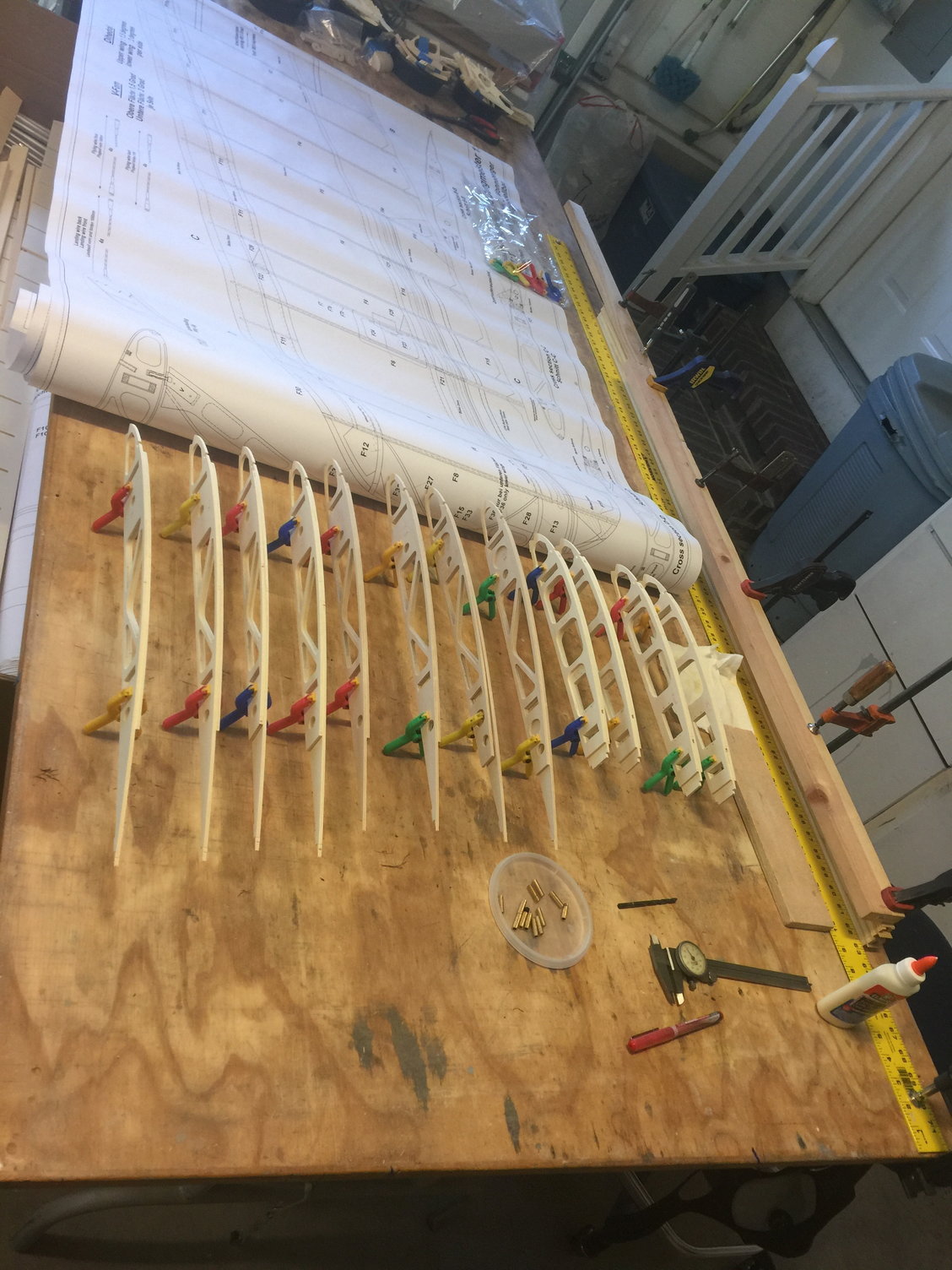
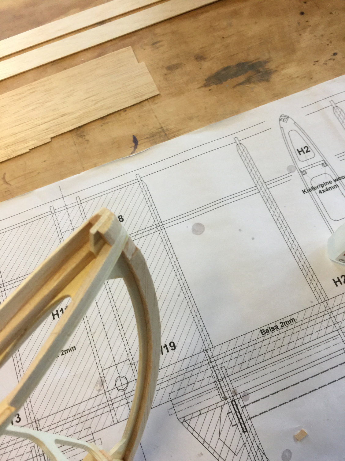
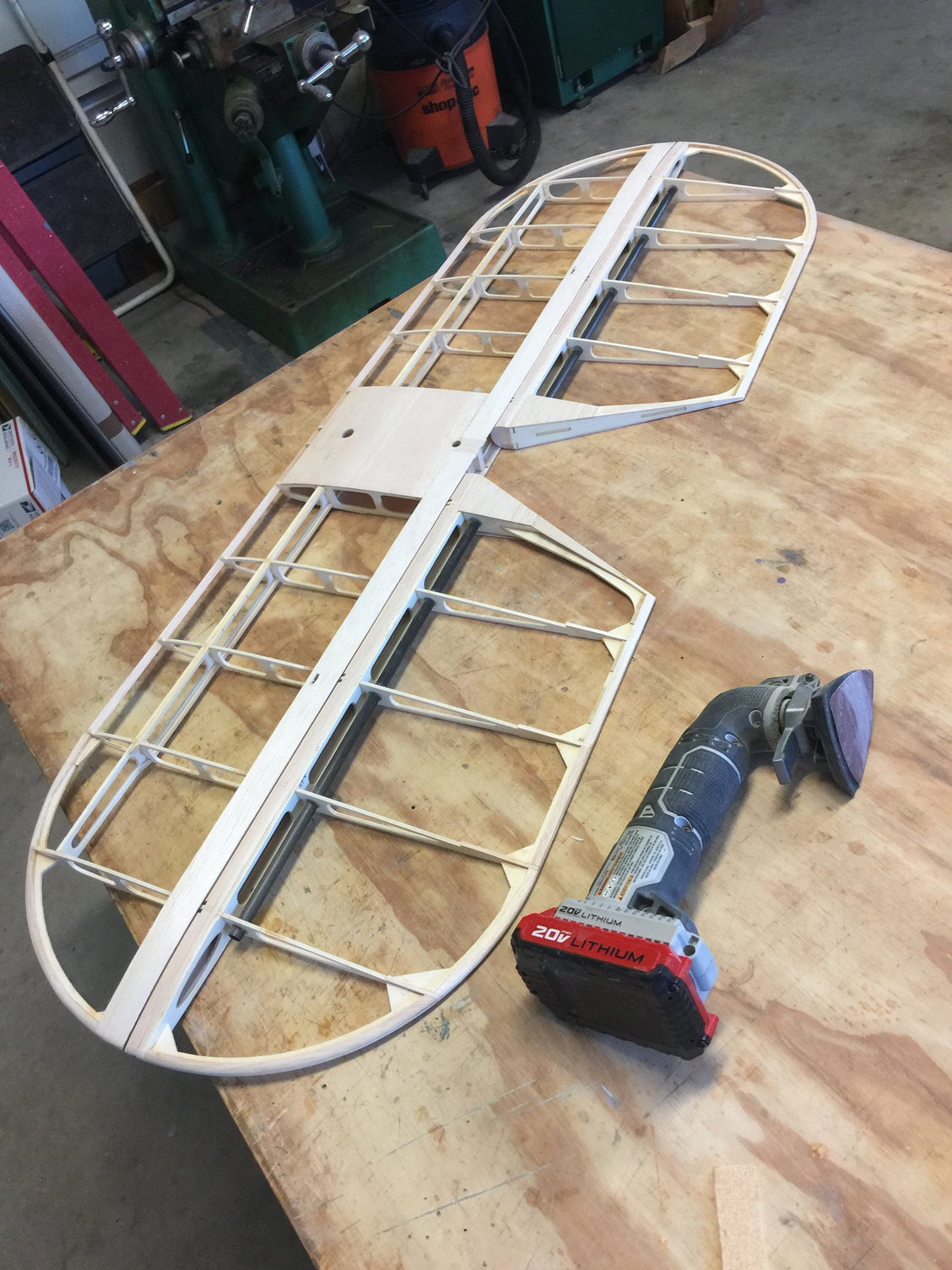
In this pic you see the wing parts all cut out of their sheets and layed out. Plan on spending a day or two just on this process. Upper left you can see the 1mm sheer-web sheets. One is perfect, the other is cut too tall. To the right of them you'll see the wing jig pieces. These work fantastically!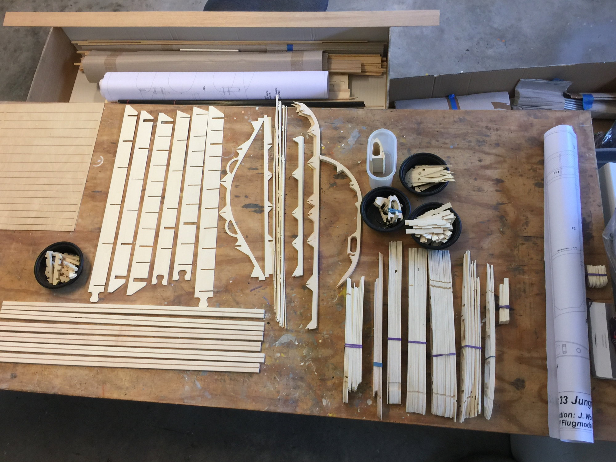
The following users liked this post:
Steve (05-12-2022)
11-14-2021, 04:09 AM
#5
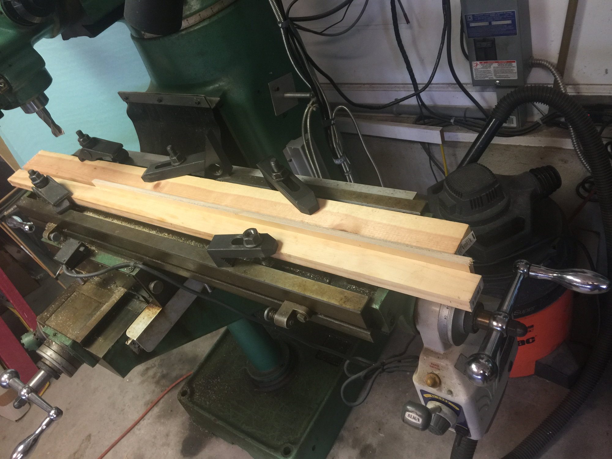
This is how I fixed the oversized sheer-webs. I cut them out and stacked them. Then I sandwiched them between a pair of 1/2x3 boards on my milling machine table. Then I carefully machined off somewhere around .050 thousandths off them. Not an insignificant amount! The pic would be easier to understand if you had the oversize webs in your hand, I'm sure. I can't imagine having to hand sand that much off of them - grrrrrr!!
The following users liked this post:
Steve (05-12-2022)
The following users liked this post:
Steve (05-12-2022)
11-14-2021, 04:23 AM
#7
I don't think the wings need much comment except to say you only get a right side plan view of the wing to build over. Jan used "salad oil" (at least that's what Google Translator called it) to make his plan more transparent for flipping and building the left sides. I really didn't want to introduce that much oil into my build environment so I laid the plan over some polyethylene sheet and saturated it with slightly thinned West Systems epoxy. Once cured, I peeled off a very nice, durable plan. This worked amazingly well and brought the ink right through to the other side. Edit: If you verify that you are building one of these kits and are willing to pay shipping I will send this leathery plan for you to build your wing over.
Last edited by mitchilito; 11-14-2021 at 02:57 PM.
The following users liked this post:
Steve (05-12-2022)
11-14-2021, 04:32 AM
#8
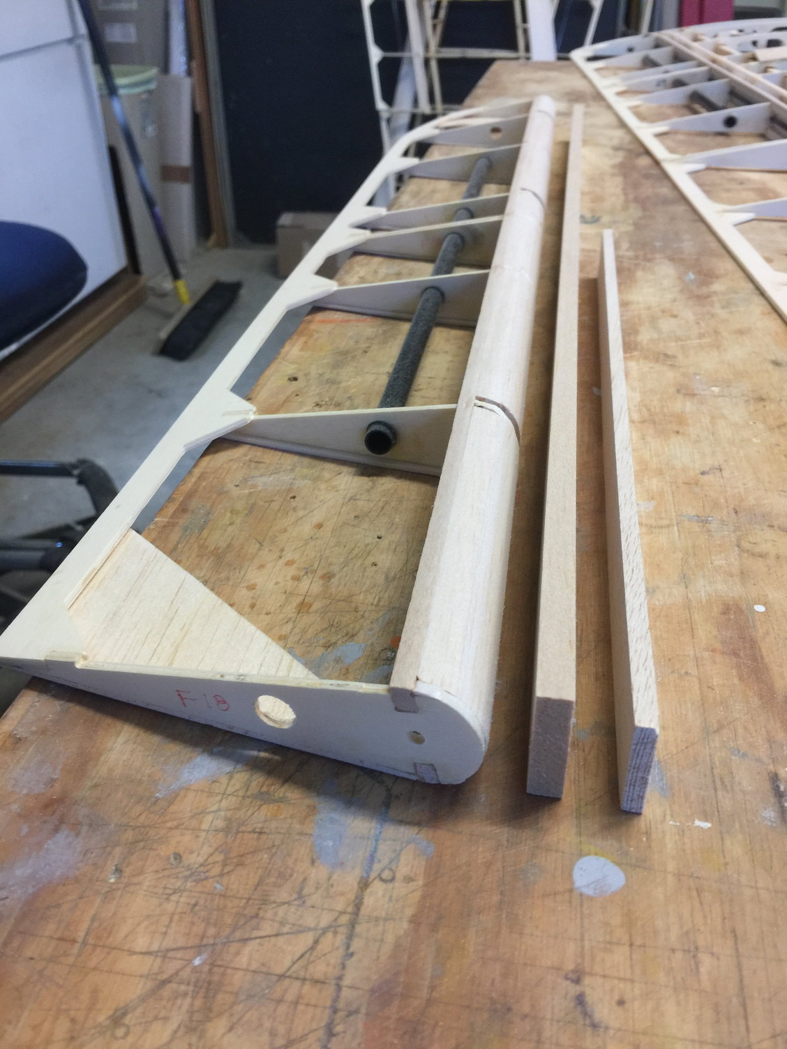
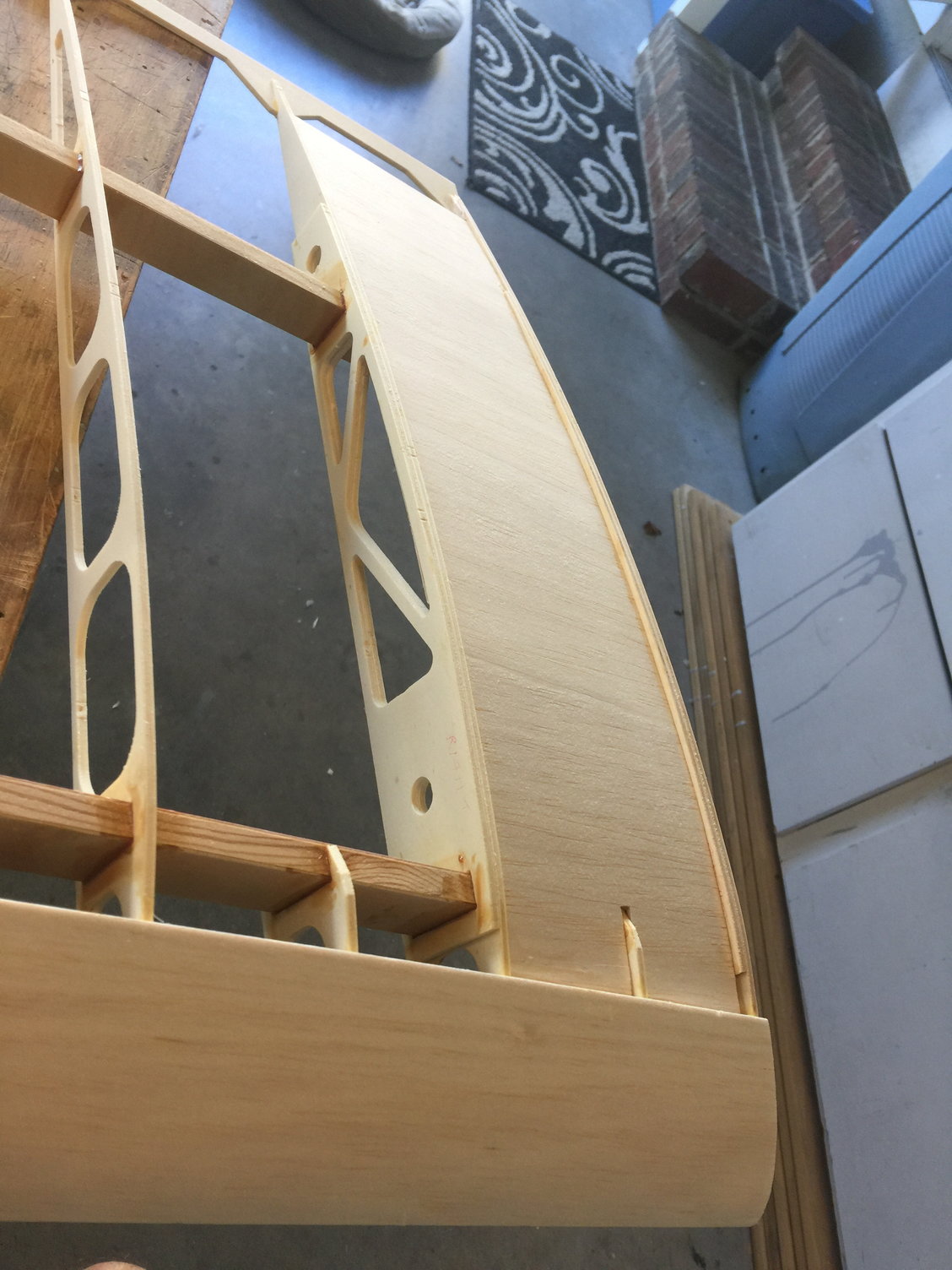
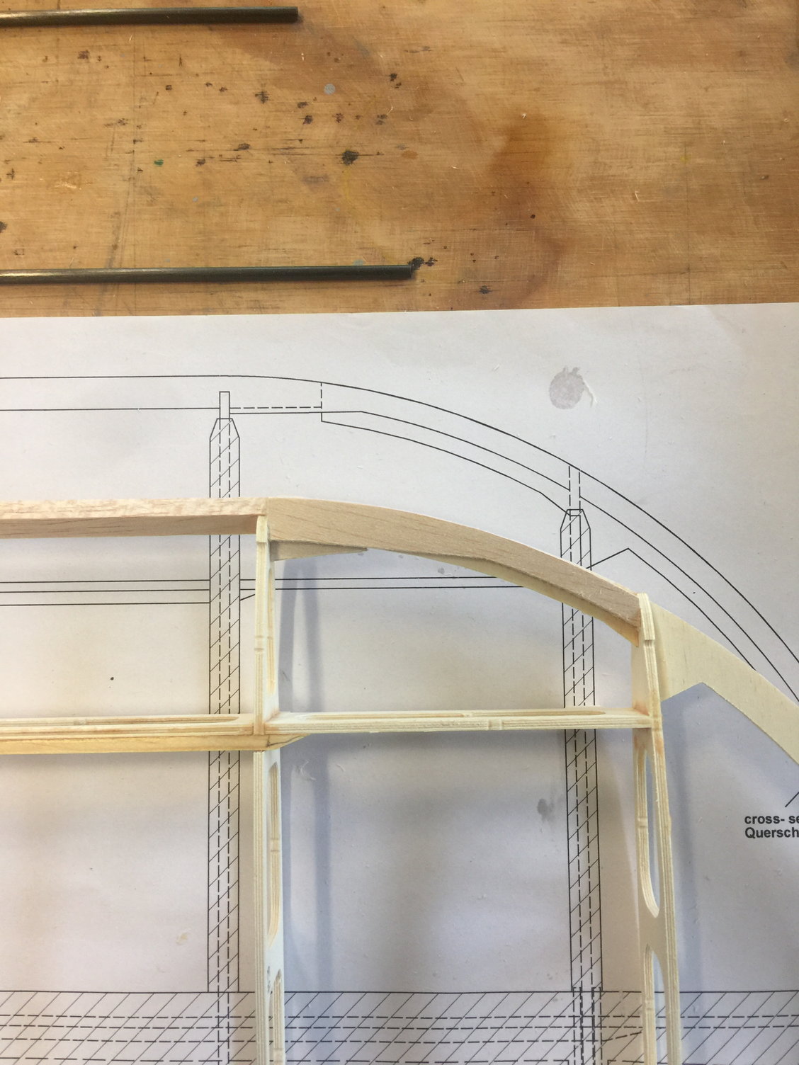
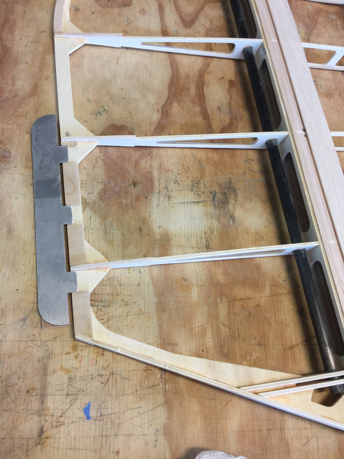
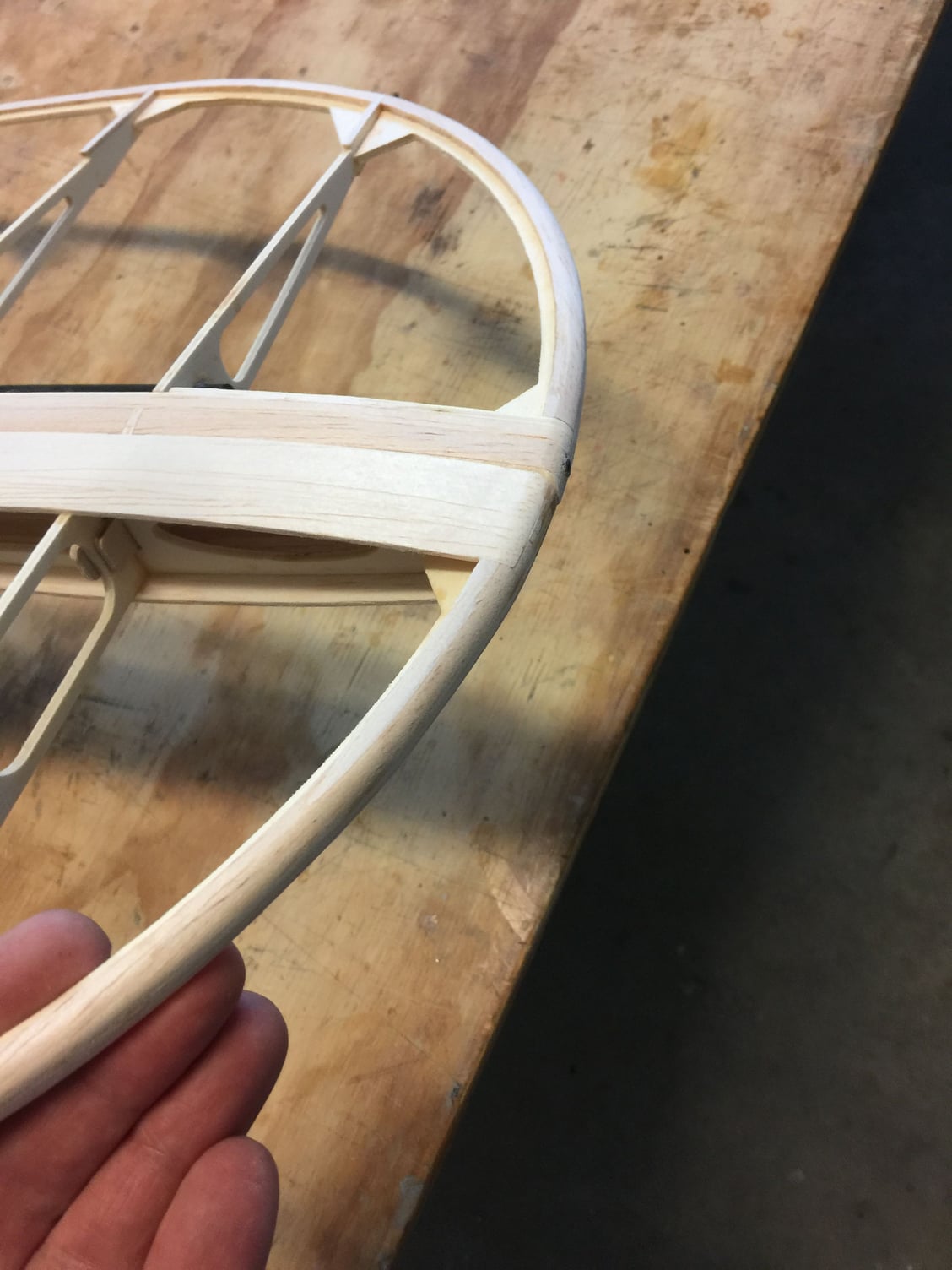
One last thing I will mention about the wing build: I couldn't figure out how JW wanted the outboard leading edge spar to join the plywood wing tip part. You can see in the pic that the wing tip plywood terminates about 1.5 inches short of the LE spar. I went ahead and made a 3mm thick trapazoid (I think that might be the term) shaped piece of hard balsa to fill that gap and add strength to the joint. This all gets laminated with soft balsa capping anyway and is shaped up nicely in the end.
Last edited by mitchilito; 11-14-2021 at 04:34 AM.
11-14-2021, 05:00 AM
#9
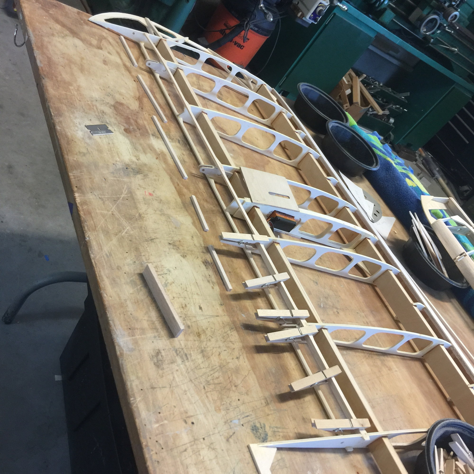
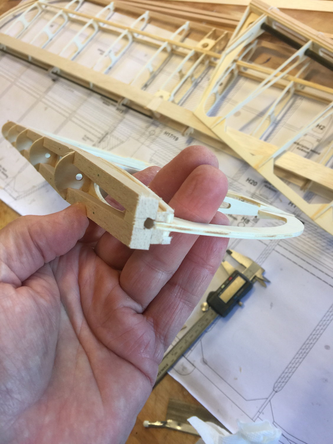
Now for the fun part (NOT!!): fitting the ailerons. This is where Jan's build thread went silent and I think I know why. Because there is no good way to do it. I will explain, more or less how I did it but each builder is really on his own here. I found out over the course of the process that I couldn't really figure out a perfect process for this step - and I had FOUR different chances to get it perfect!!
Here is the initial assembly. (the horn is just temporarily slipped in for fit)
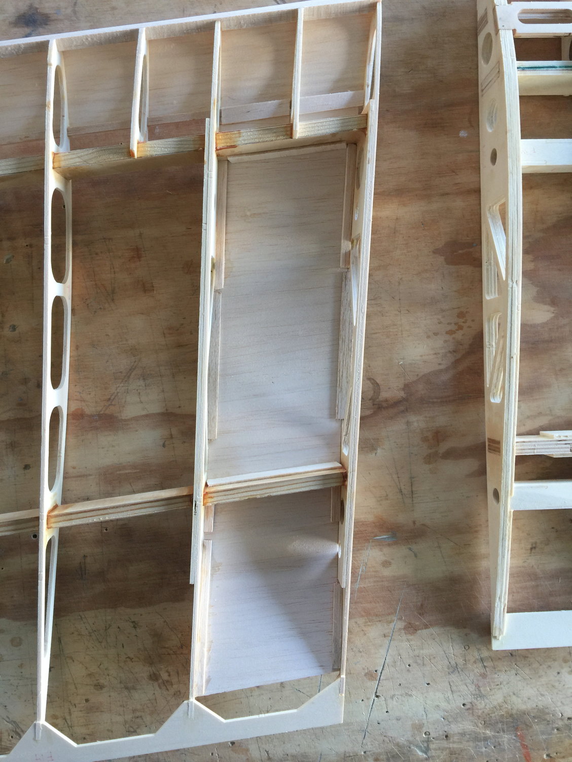
Look closely at the next photo. You will see how I removed all unnecessary plywood on the back of the wing ribs in preparation for aileron fitting. This is the way to go:
The plans did not match the aileron ribs where they show the 7x5mm cross spars and the placement of the 8x8mm and 30mm aileron leading edges. Now, maybe there IS a way to get it to work out but I could not figure it out. I can tell you most assuredly the plan placement of the 7x5s don't match the machined parts. How about another grrrrrrr.
Again, don't take my word for it. See if you can figure it out. In the end I never even used the 8x8 balsa sticks. Instead, I cut up the 30mm LE pieces and glued them directly on to the 7x7s and then capped that with som 1/4 soft (ish) balsa I bought elsewhere. See here:
Here is the initial assembly. (the horn is just temporarily slipped in for fit)
Look closely at the next photo. You will see how I removed all unnecessary plywood on the back of the wing ribs in preparation for aileron fitting. This is the way to go:
The plans did not match the aileron ribs where they show the 7x5mm cross spars and the placement of the 8x8mm and 30mm aileron leading edges. Now, maybe there IS a way to get it to work out but I could not figure it out. I can tell you most assuredly the plan placement of the 7x5s don't match the machined parts. How about another grrrrrrr
.Again, don't take my word for it. See if you can figure it out. In the end I never even used the 8x8 balsa sticks. Instead, I cut up the 30mm LE pieces and glued them directly on to the 7x7s and then capped that with som 1/4 soft (ish) balsa I bought elsewhere. See here:
Last edited by mitchilito; 11-14-2021 at 02:27 PM.
The following users liked this post:
Steve (05-12-2022)
11-14-2021, 05:21 AM
#10
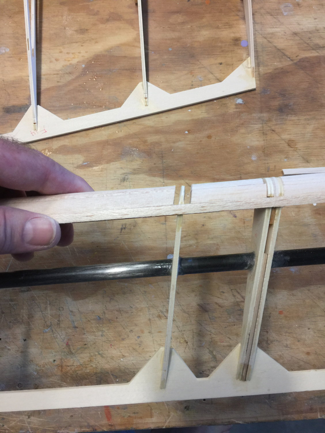
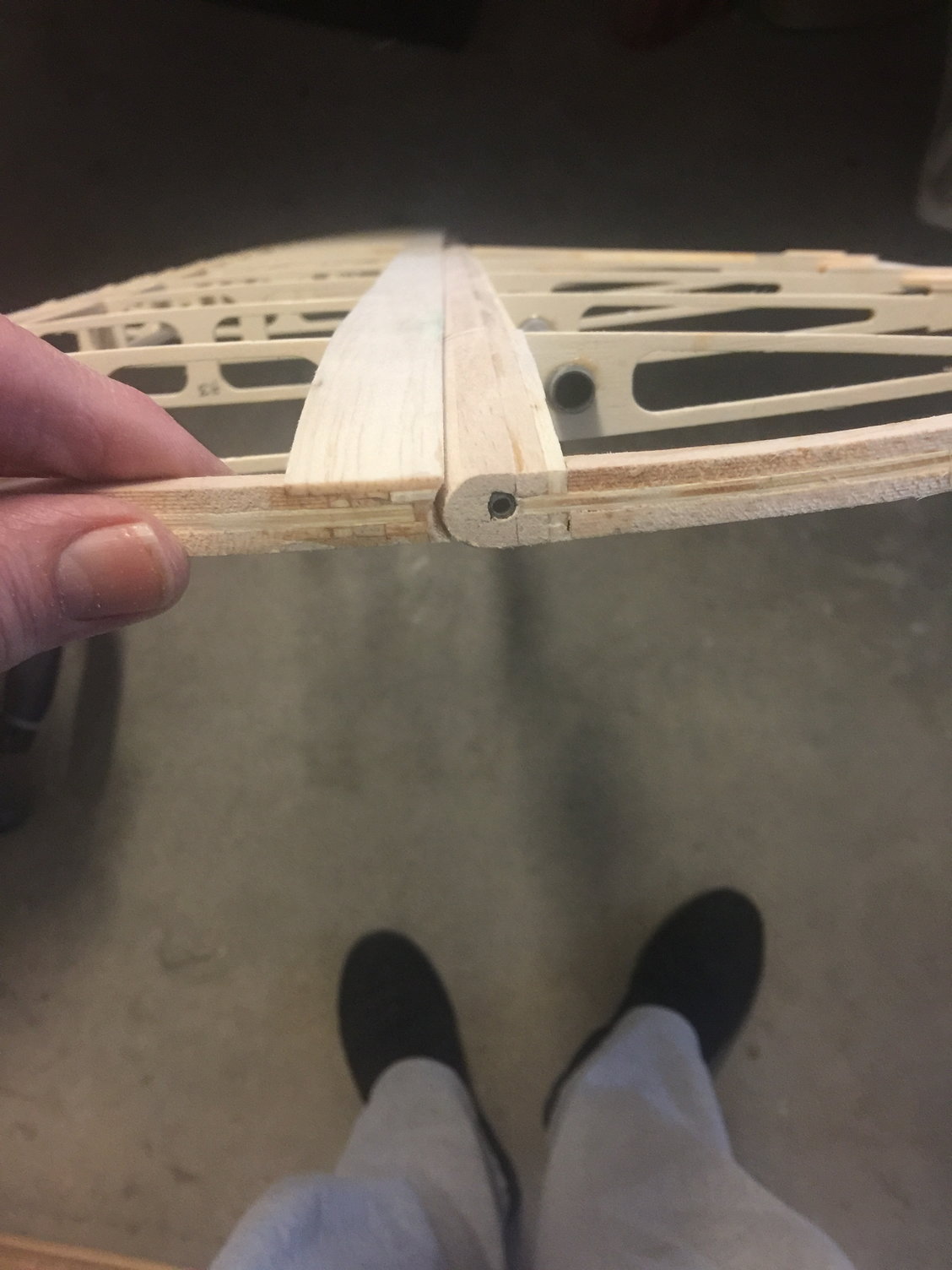
Here is something I'd like to pass along. Because the ailerons are swept, the geometry of their swing moves their hinge parts into the wing hinge parts creating interference (you'll see what I mean). So to facilitate the smoothest, largest travel possible MAKE SURE the spaces on either side of the aileron hinge points (which are the leading edges of three of the aileron ribs) are wide enough to NOT touch the sets of plywood hinge points coming from the wing. You probably have to see it to understand. And another thing to free them up is to TAPER the aileron hinge point leading edges as shown in this picture. When I first realized what the designer had designed I was appalled. But after freeing it up and getting my brain wrapped around it I now think it's a pretty cool design. The down side is you just can't get as much throw as you may like. Some biding is unavoidable.
Here you see how wide the hinge clearance spaces are and how I tapered the nose of the plywood rib leading edges. This is very necessary.
Boy, I sure wish I had this thread when I started this build!!
Here you see how wide the hinge clearance spaces are and how I tapered the nose of the plywood rib leading edges. This is very necessary.
Boy, I sure wish I had this thread when I started this build!!
Last edited by mitchilito; 11-14-2021 at 02:25 PM.
The following users liked this post:
Steve (05-12-2022)
11-17-2021, 06:12 AM
#11
If I had to do the fitting of the ailerons all over again this is roughly what I would do. First thing I would do is sand the leading edges of the ailerons themselves about 2mm larger than final size. This is going to be your final clearance when you sand it off so it is very necessary. If you look at these pics you will see that ultimately, the aileron leading edges get sanded right down to the rib noses - so add two millimeters to this, then proceed.
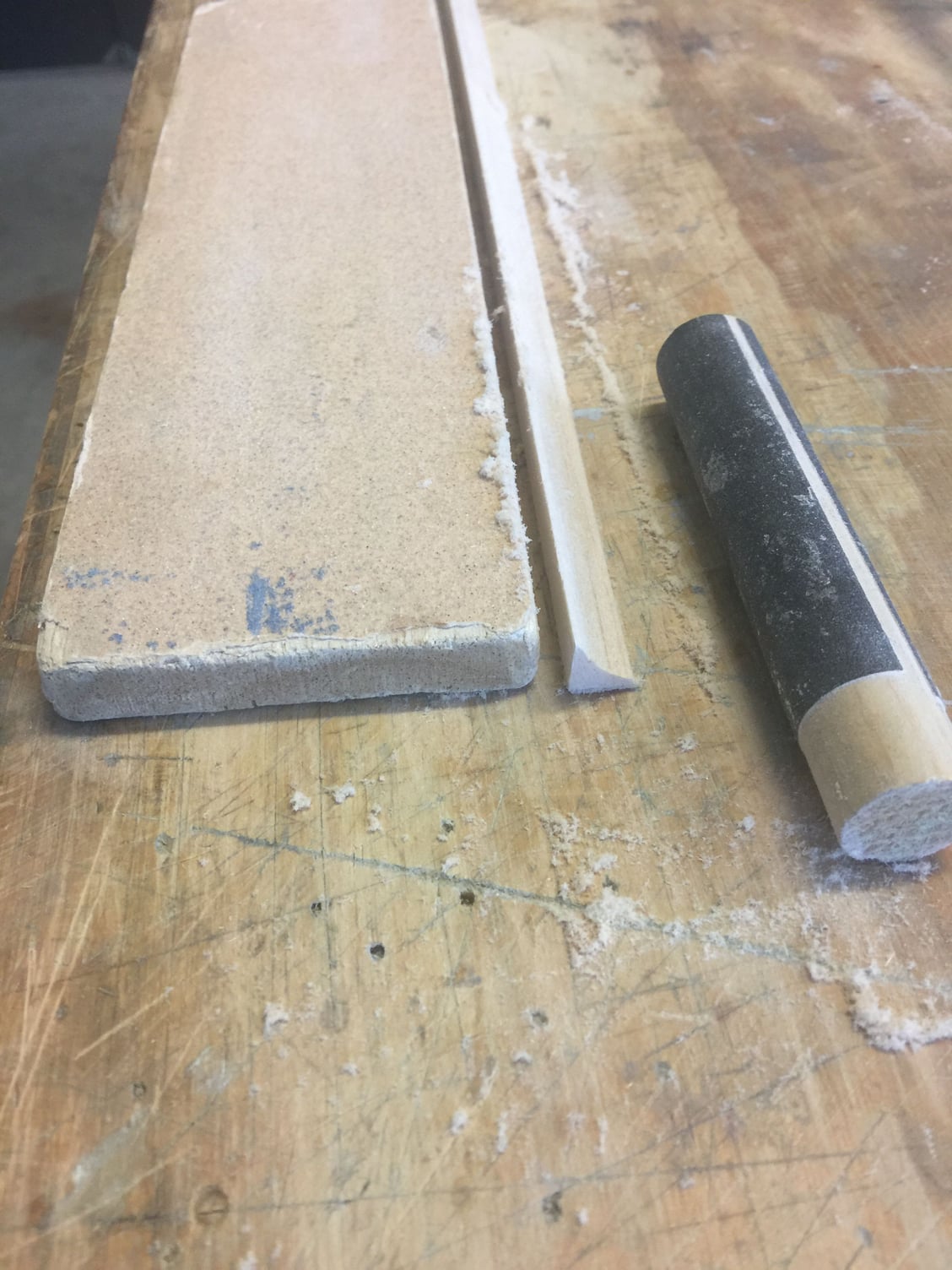
Next, sand concave one surface of the triangle stock. I made a special sanding dowl and sanded against a board (which happened to be my sanding block):
The plans show the triangle stock attaching to the back of the plywood piece on the wing (I think it's F16) and the thin balsa cover over it. That did not seem like enough surface to me so I added some light 1/4 square sticks between the ribs to also glue to. Quite possibly unnecessary but the additional weight is insignificant:
I clipped on a piece of liteply to the back of the wing to show the angle of the back face of the parts we're discussing. This is critical: the face of these parts MUST be 90 degrees to the surface of the wing ribs as they taper toward the rear. If they are not 90 degrees then when you glue on the triangles, the top surface of the triangle is not going to match the adjoining wing sheeting. I guess it could still be sanded to match but this part is going to make all the difference in how the wing/aileron interface looks so start with if very close if you can. ALSO: you will need to make sure when you glue the triangle stock to the interface that at least a little of it stands higher than the wing sheeting (of course). I found that fitting the ailerons took significantly more time than actually building the wing itself!

Here I've clipped a board to the aft face
Here's what I saw: the angle it too acute. See how the top aft surface of the wing rib slopes down? We want the angle of the top of the triangle stock, when glue on, to follow this slope so it matches the wing sheeting. The aft face of the wing openings must be sanded to accommodate.
Then you will glue the triangle stock on, finish sand the clearance into the ailerons and sand the triangles to match the wings. Good luck. . . . . . . .
Here's what it looks like when done:
Whew! I'm glad that's over with.
Next, sand concave one surface of the triangle stock. I made a special sanding dowl and sanded against a board (which happened to be my sanding block):
The plans show the triangle stock attaching to the back of the plywood piece on the wing (I think it's F16) and the thin balsa cover over it. That did not seem like enough surface to me so I added some light 1/4 square sticks between the ribs to also glue to. Quite possibly unnecessary but the additional weight is insignificant:
I clipped on a piece of liteply to the back of the wing to show the angle of the back face of the parts we're discussing. This is critical: the face of these parts MUST be 90 degrees to the surface of the wing ribs as they taper toward the rear. If they are not 90 degrees then when you glue on the triangles, the top surface of the triangle is not going to match the adjoining wing sheeting. I guess it could still be sanded to match but this part is going to make all the difference in how the wing/aileron interface looks so start with if very close if you can. ALSO: you will need to make sure when you glue the triangle stock to the interface that at least a little of it stands higher than the wing sheeting (of course). I found that fitting the ailerons took significantly more time than actually building the wing itself!
Here I've clipped a board to the aft face
Here's what I saw: the angle it too acute. See how the top aft surface of the wing rib slopes down? We want the angle of the top of the triangle stock, when glue on, to follow this slope so it matches the wing sheeting. The aft face of the wing openings must be sanded to accommodate.
Then you will glue the triangle stock on, finish sand the clearance into the ailerons and sand the triangles to match the wings. Good luck. . . . . . . .
Here's what it looks like when done:
Whew! I'm glad that's over with.
Last edited by mitchilito; 11-18-2021 at 01:36 AM.
The following users liked this post:
Steve (05-12-2022)
The following users liked this post:
Steve (05-12-2022)
11-17-2021, 08:27 AM
#13
And finally, with respect to the wings: the plans seem to make it pretty clear that the top of the top wings get sheeted on the OUTSIDE of the ribs, which would keep the covering from being able to drape down like it does on all the other ribs. Even the instructions mention something (as I said the translation is not good) about sheeting so the covering can arc down. Yet the plans show it on the outside. And this is not the first or last time the instructions don't match the plans, don't match the drawings etc.
ANYWAY, with that said, I did an exhaustive review of full scale Jungmeister pictures on line and one can clearly see that the covering drapes between ALL the ribs across the top of the wings and center section. Interestingly enough, they set the top center section to have the sheeting recessed. But not the wing inboard roots. Go figure.
SO: I recessed the wing sheeting like this:
You have to get a little creative here
Last edited by mitchilito; 11-18-2021 at 01:37 AM.
The following users liked this post:
Steve (05-12-2022)
The following users liked this post:
Steve (05-12-2022)
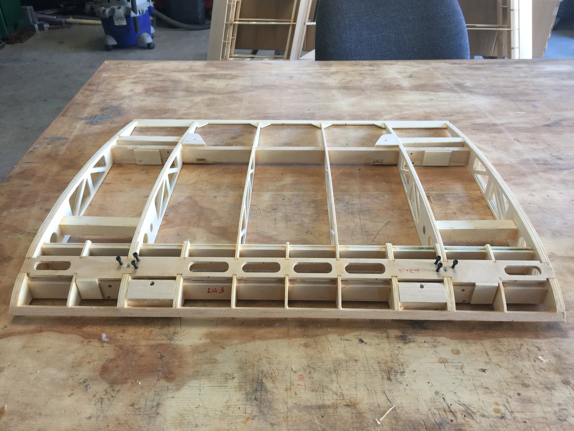
11-17-2021, 02:55 PM
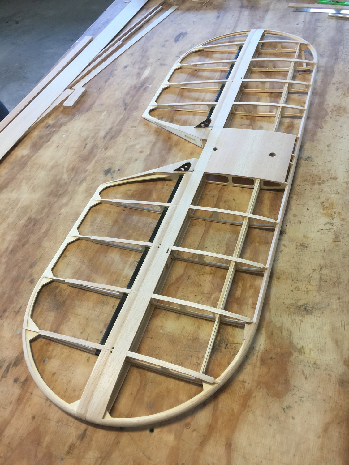
#15
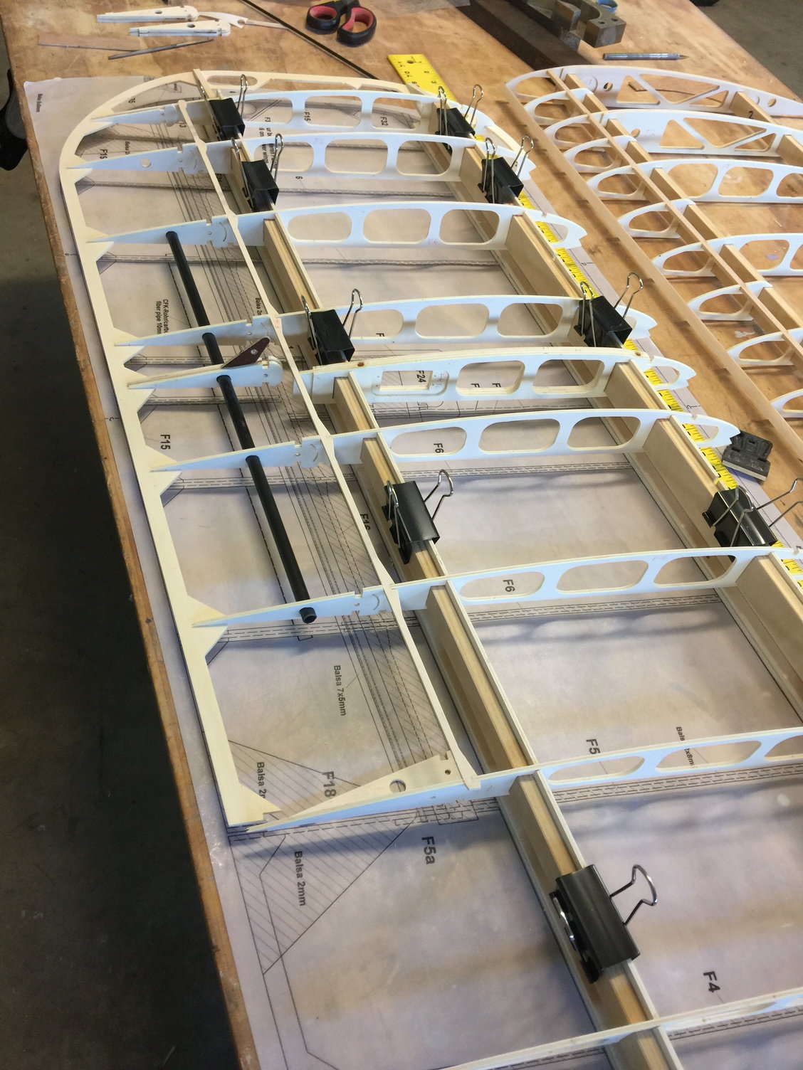
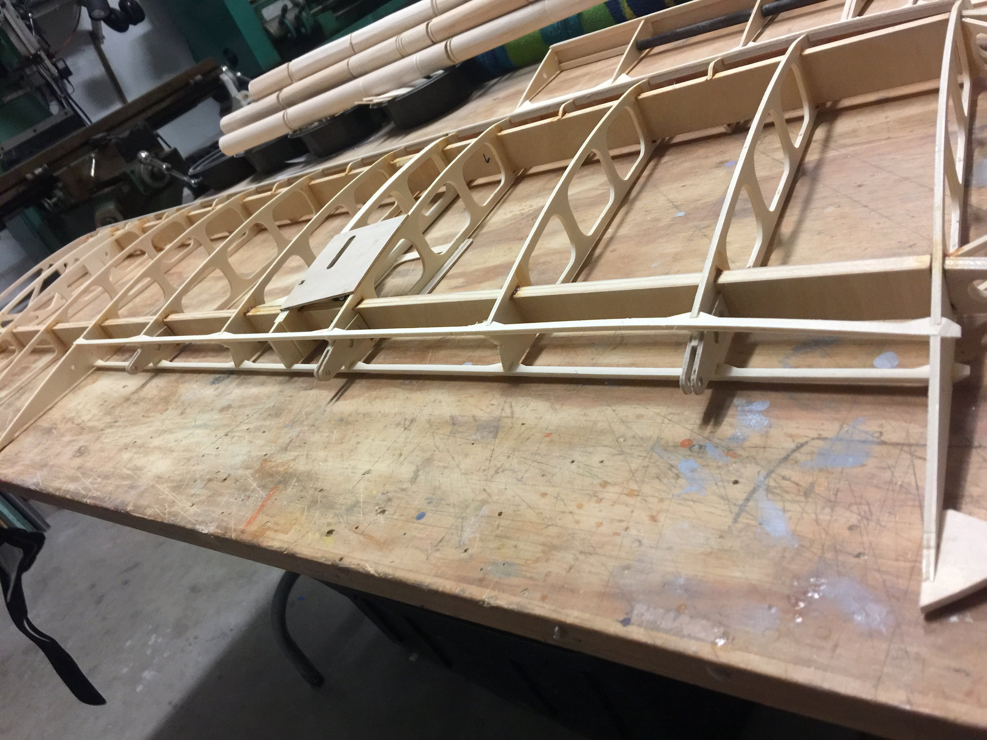
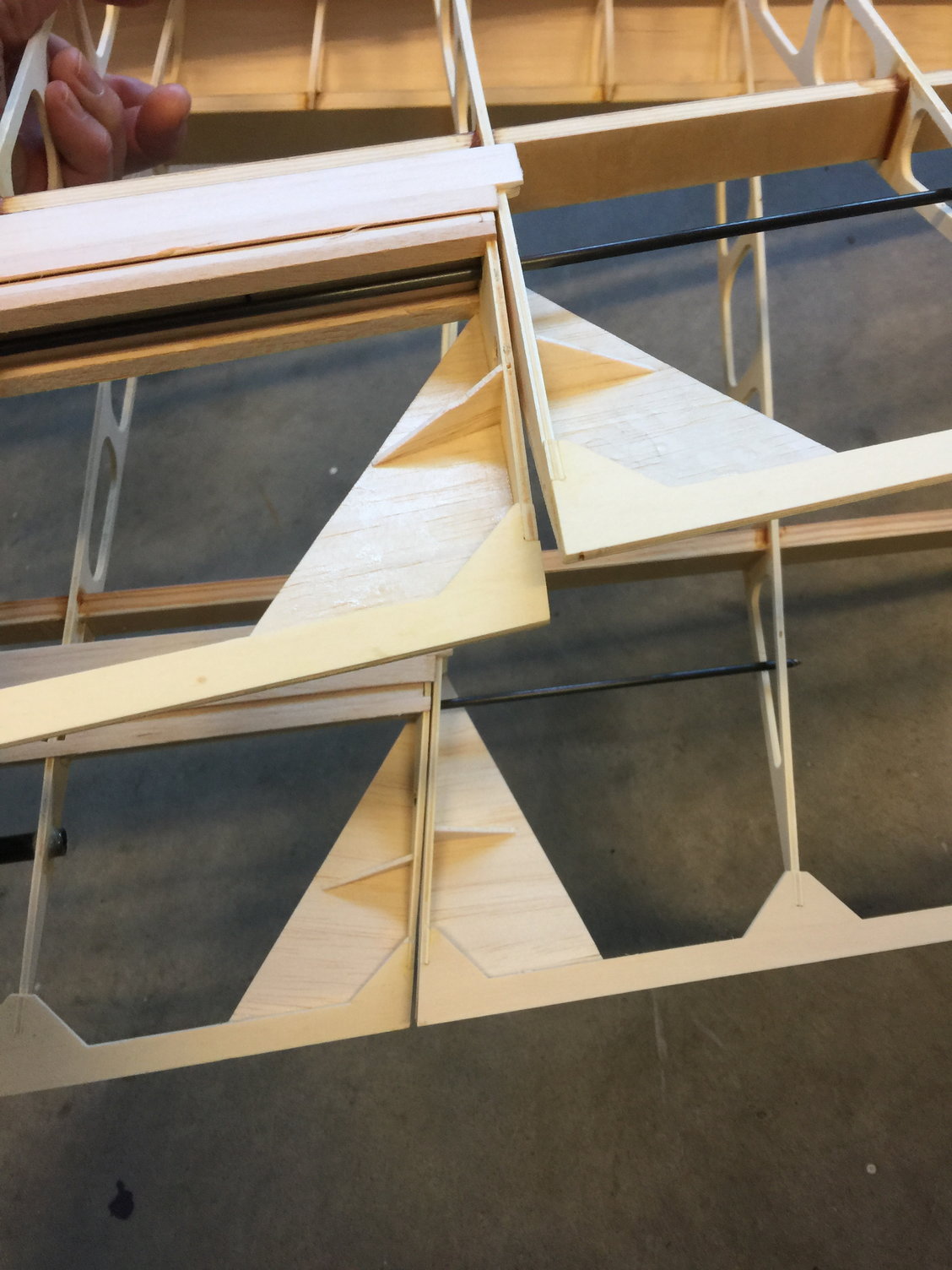
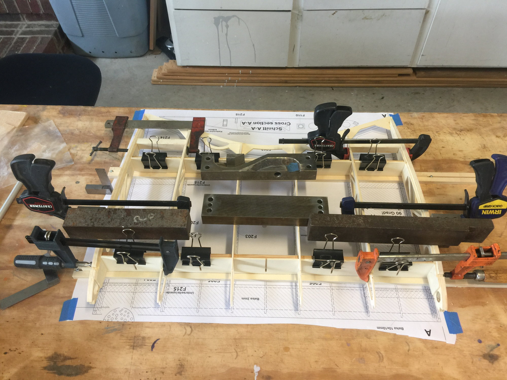
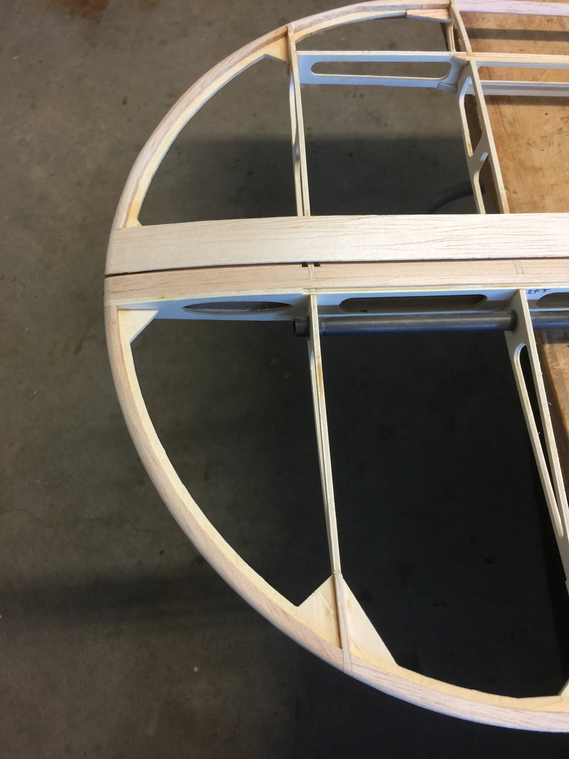
But the bottom center section is whole other beast. It's very busy and the best way I found to figure out how it all goes together is to dry-assemble it. One can almost entirely assemble it without any glue. Here's the hot tip for this part: the instructions casually instruct you to begin assembly by putting the ribs into the center section jigs - the same jigs you just took the top center section out of. Well guess what? The bottom section is wider than the top so it will not fit into the jigs. Sheesh.
The solution is to simply remove the outermost jig parts (the ones with the 45 degree ends ) to make clearance for the added end width. Make sure you leave a flat surface where the outer ribs will sit. I also took this opportunity to sand the 1.5 degrees the plan calls for into the jig ends.
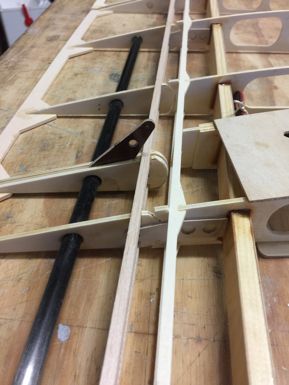
In this pic you can see the .100 thousandths thick steel plates I machined to use as nut plates (I bonded them in with tons of structural adhesive). Plane old blind nuts would work but I didn't have any kicking around. Plus, I'm going to want to lock tight these flying wire screws in the end and plan to use plenty of lock tight. I've had BAD experiences using lock tight with blind nuts - hence the plates. I also bonded ply plates here and there to beef up critical parts.
The solution is to simply remove the outermost jig parts (the ones with the 45 degree ends ) to make clearance for the added end width. Make sure you leave a flat surface where the outer ribs will sit. I also took this opportunity to sand the 1.5 degrees the plan calls for into the jig ends.
In this pic you can see the .100 thousandths thick steel plates I machined to use as nut plates (I bonded them in with tons of structural adhesive). Plane old blind nuts would work but I didn't have any kicking around. Plus, I'm going to want to lock tight these flying wire screws in the end and plan to use plenty of lock tight. I've had BAD experiences using lock tight with blind nuts - hence the plates. I also bonded ply plates here and there to beef up critical parts.
Last edited by mitchilito; 11-18-2021 at 01:40 AM.
The following users liked this post:
Steve (05-12-2022)
11-17-2021, 03:07 PM
#16
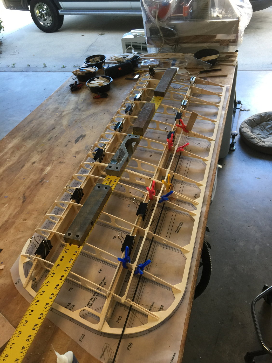
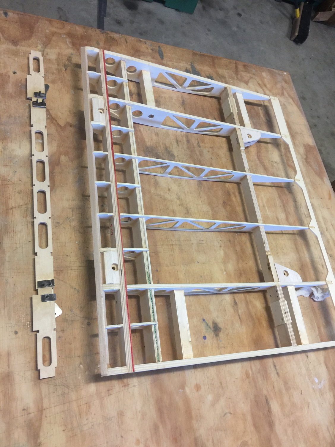
And here it is prior to sheeting. Look close and you will see how I bonded ply plates to structurally connect the two main cross member parts (F117 and F124). This requires sanding the faces of the two projections that stick out of F124 at an angle that is flush with F117. You will wind up with a perfect flat surface to bond a plate onto to join these critical parts together (right where it counts).
I also didn't like the entire load of the positive flying wires working to pull F124 out of the center section so you can also see how I put a small counter sunk screw through F124 into the rib assembly underneath.
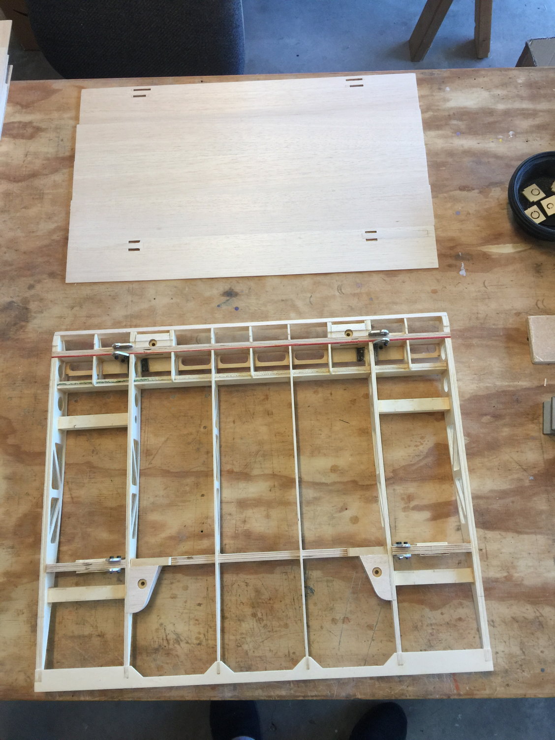
Bottom ready for sheeting
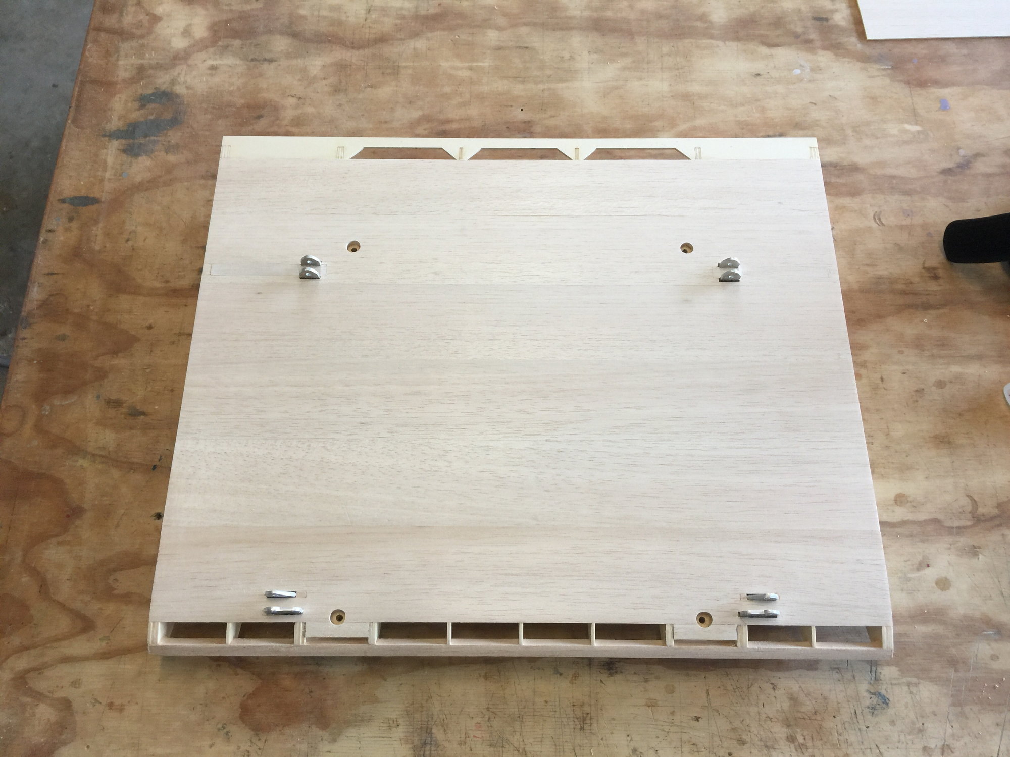
Sheeted. I did not install the F125 plates. I couldn't deduce any advantage to having them. If they were for added strength they were all wrong. Assembly is plenty strong without them
I also didn't like the entire load of the positive flying wires working to pull F124 out of the center section so you can also see how I put a small counter sunk screw through F124 into the rib assembly underneath.
Bottom ready for sheeting
Sheeted. I did not install the F125 plates. I couldn't deduce any advantage to having them. If they were for added strength they were all wrong. Assembly is plenty strong without them
Last edited by mitchilito; 11-18-2021 at 11:15 AM.
The following users liked this post:
Steve (05-12-2022)
11-17-2021, 03:24 PM
#17
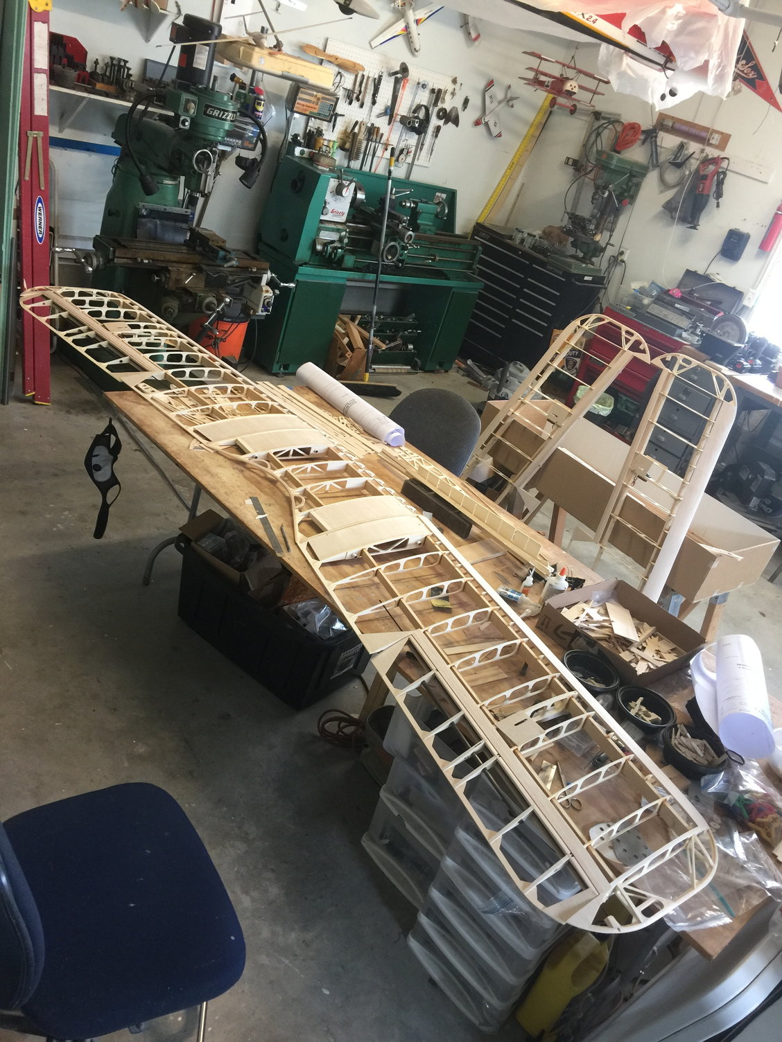
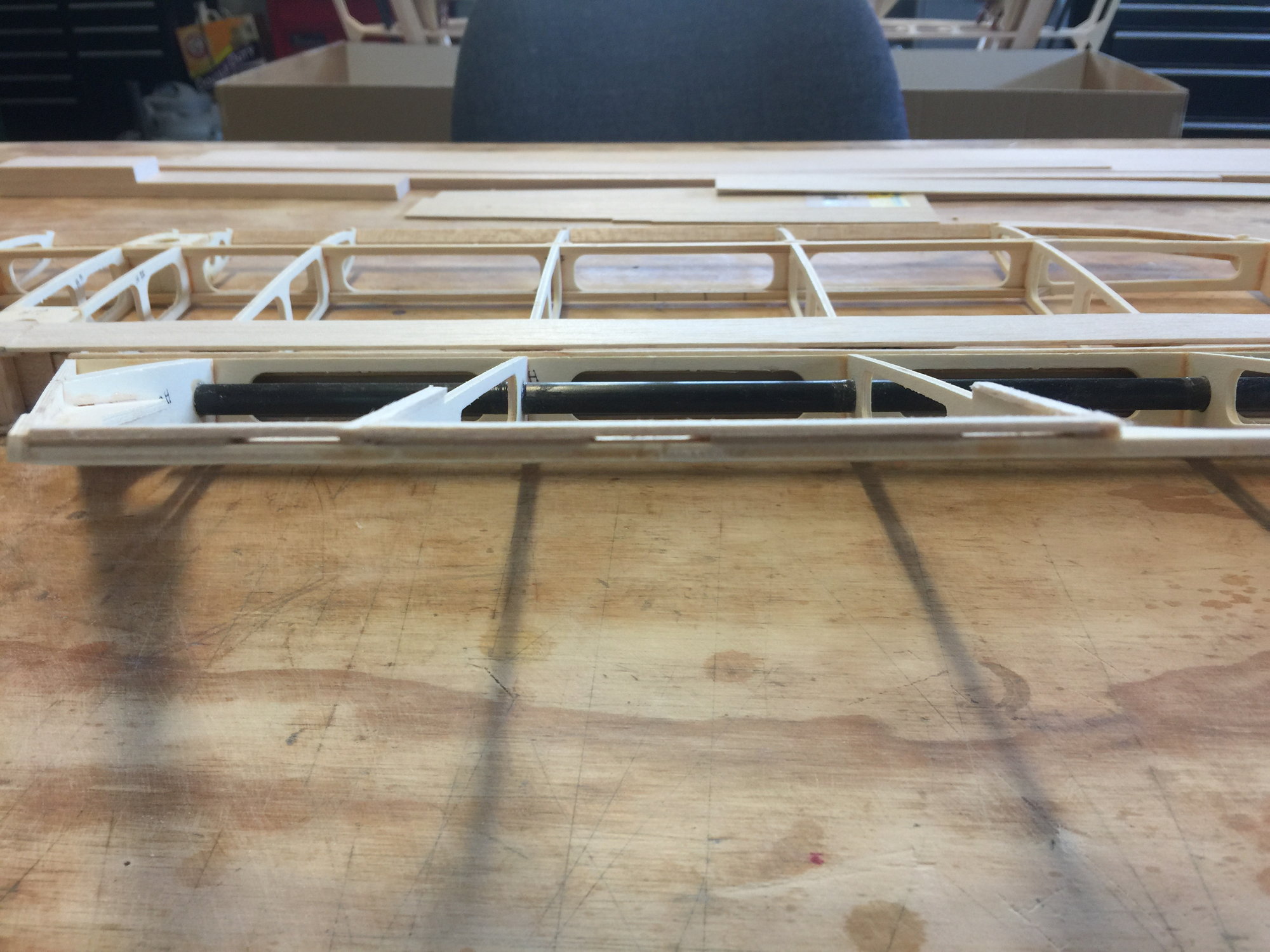
So I've been working on it for about a month and this is my total progress.
Edit: I was just looking at this picture thinking about how bare the center sections look without their sheeting applied yet. You know why it hasn't been applied? Because there isn't any in the kit! I would estimate that about 4 square feet of balsa was not supplied. I can't really figure this fact out either: the kit is so reasonbably priced that another 50 or 100 buck to put enough balsa to finish the kit would be no big deal. SO: I just bought $80 worth of beautiful hand selected balsa from Balsa USA which should be enough to finish the kit: 6 sheets of 3/32x3x48 (which is almost identical to the 3mm supplied which was just enough for the wing leading edges!). I also bought 6 sheets of 1/16x3x48 which I have a feeling I may use in other places. Who knows.
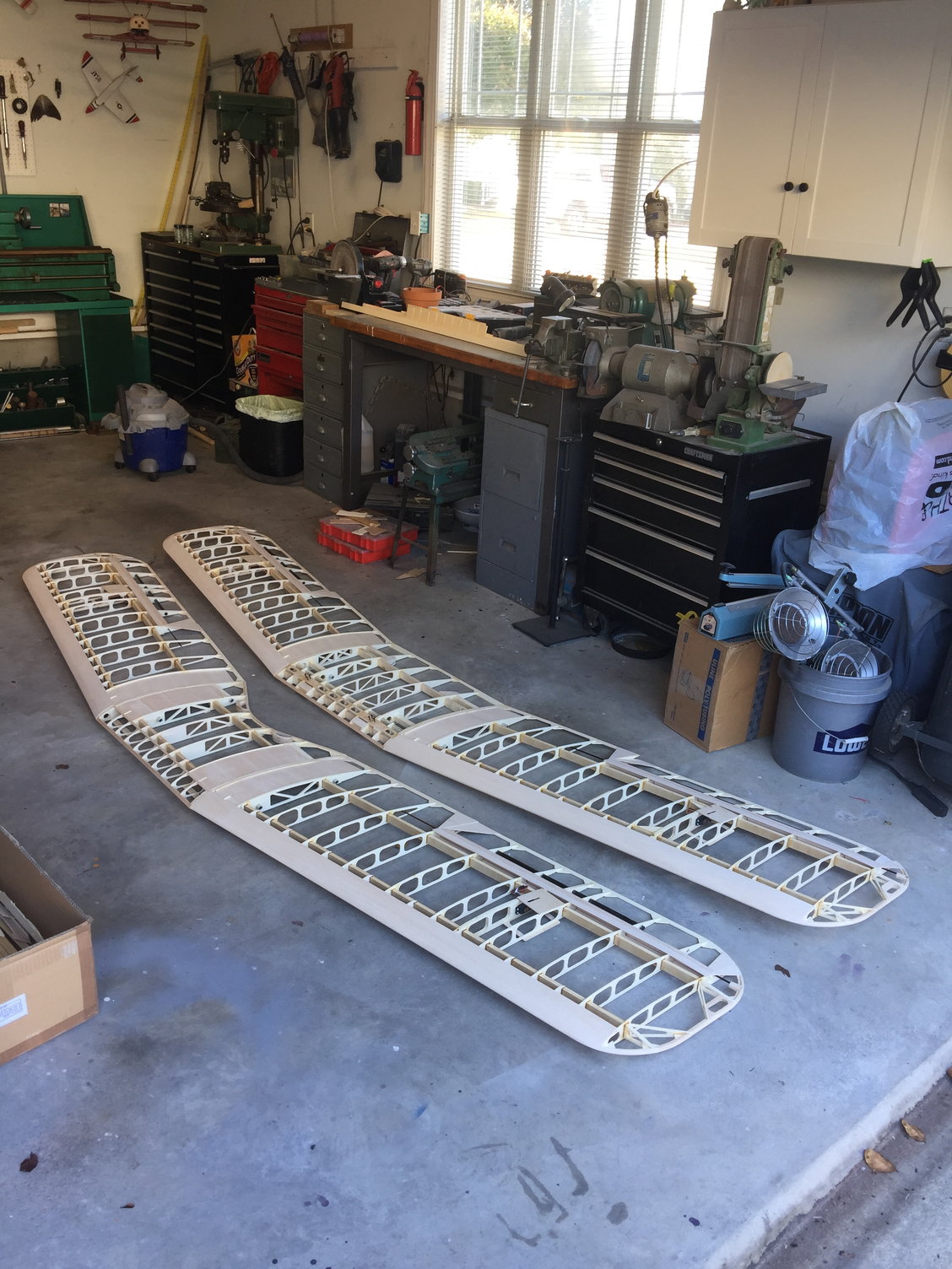
Edit: I was just looking at this picture thinking about how bare the center sections look without their sheeting applied yet. You know why it hasn't been applied? Because there isn't any in the kit! I would estimate that about 4 square feet of balsa was not supplied. I can't really figure this fact out either: the kit is so reasonbably priced that another 50 or 100 buck to put enough balsa to finish the kit would be no big deal. SO: I just bought $80 worth of beautiful hand selected balsa from Balsa USA which should be enough to finish the kit: 6 sheets of 3/32x3x48 (which is almost identical to the 3mm supplied which was just enough for the wing leading edges!). I also bought 6 sheets of 1/16x3x48 which I have a feeling I may use in other places. Who knows.
Last edited by mitchilito; 11-17-2021 at 03:38 PM.

The following users liked this post:
Steve (05-12-2022)
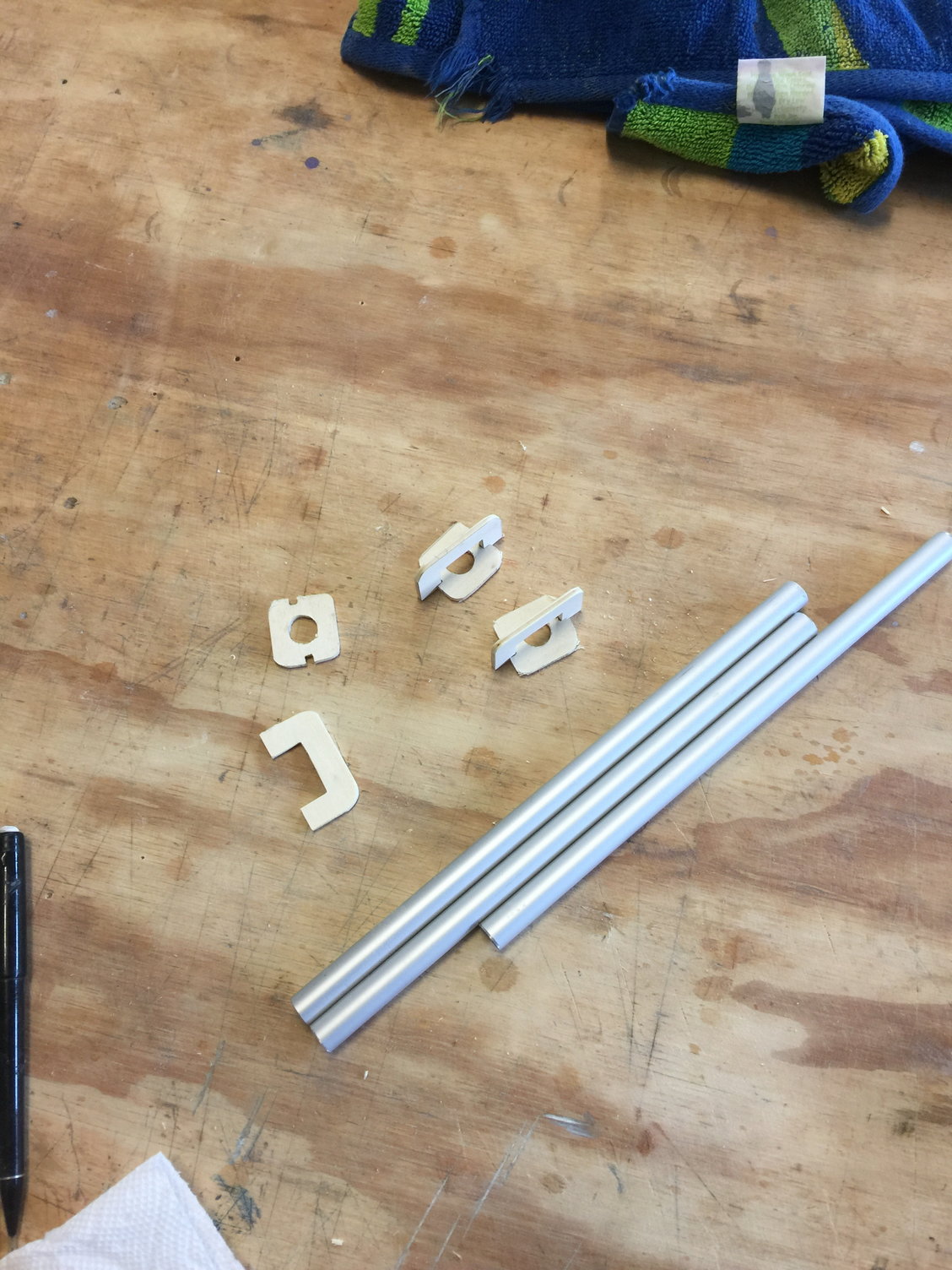
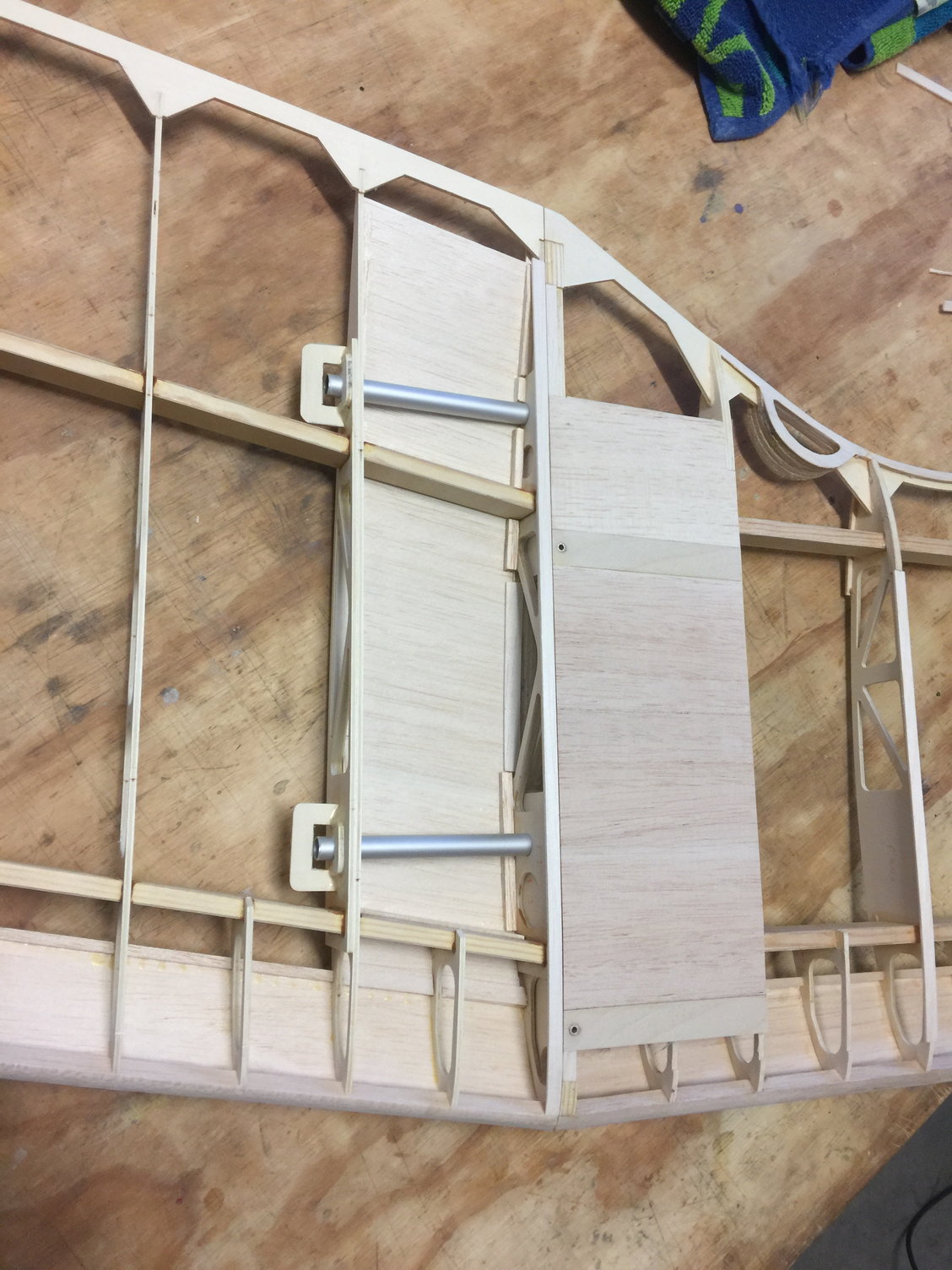
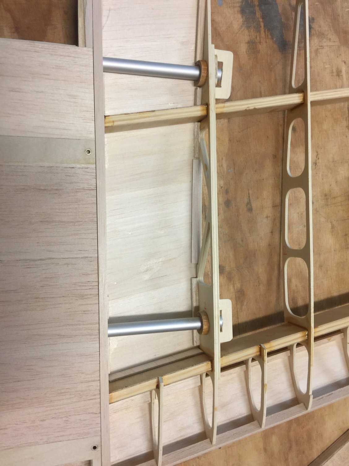
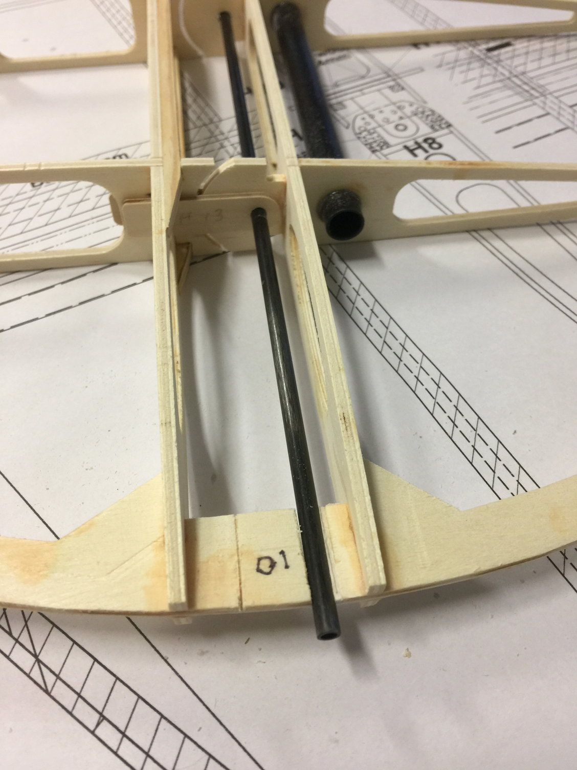
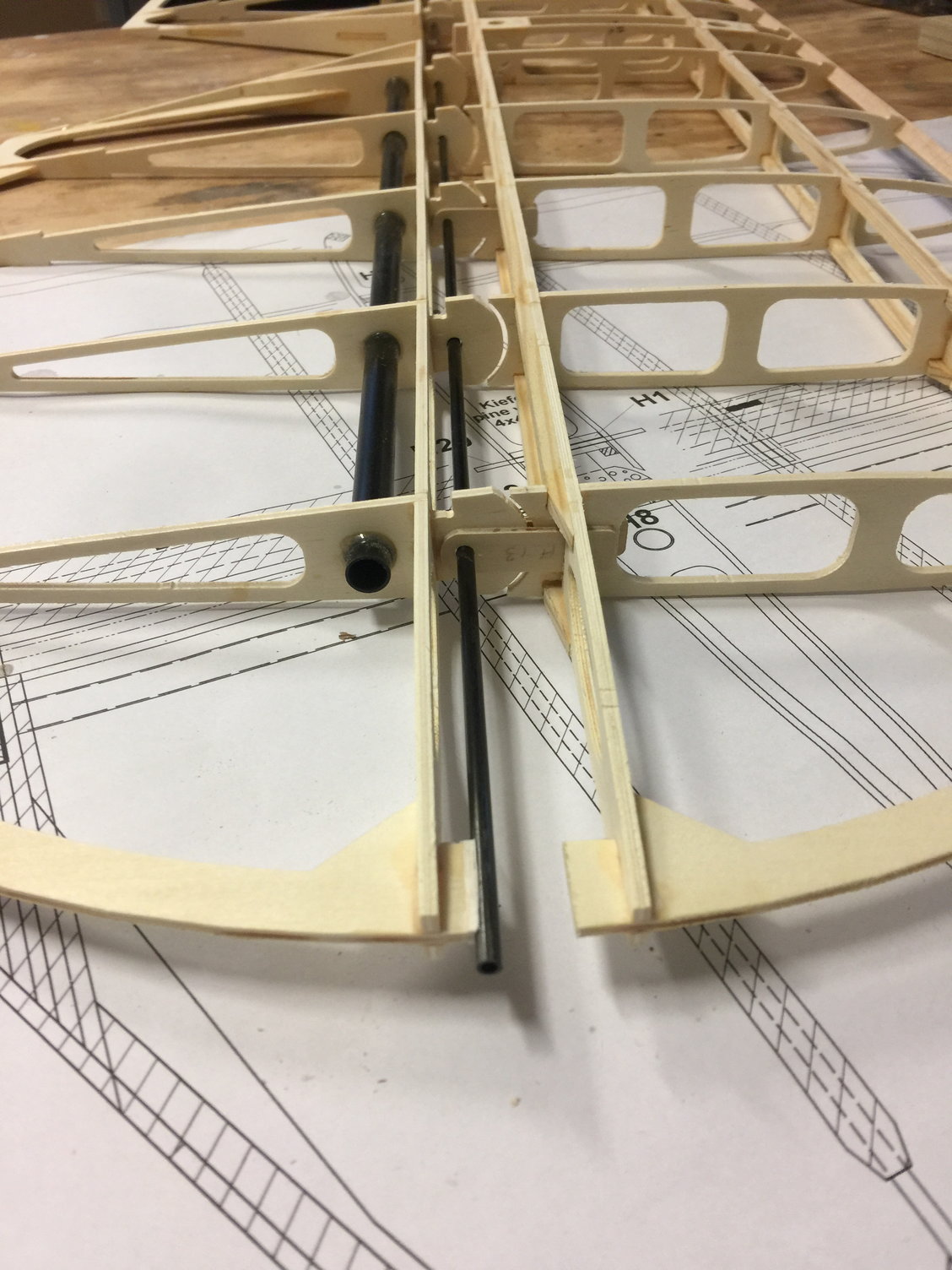
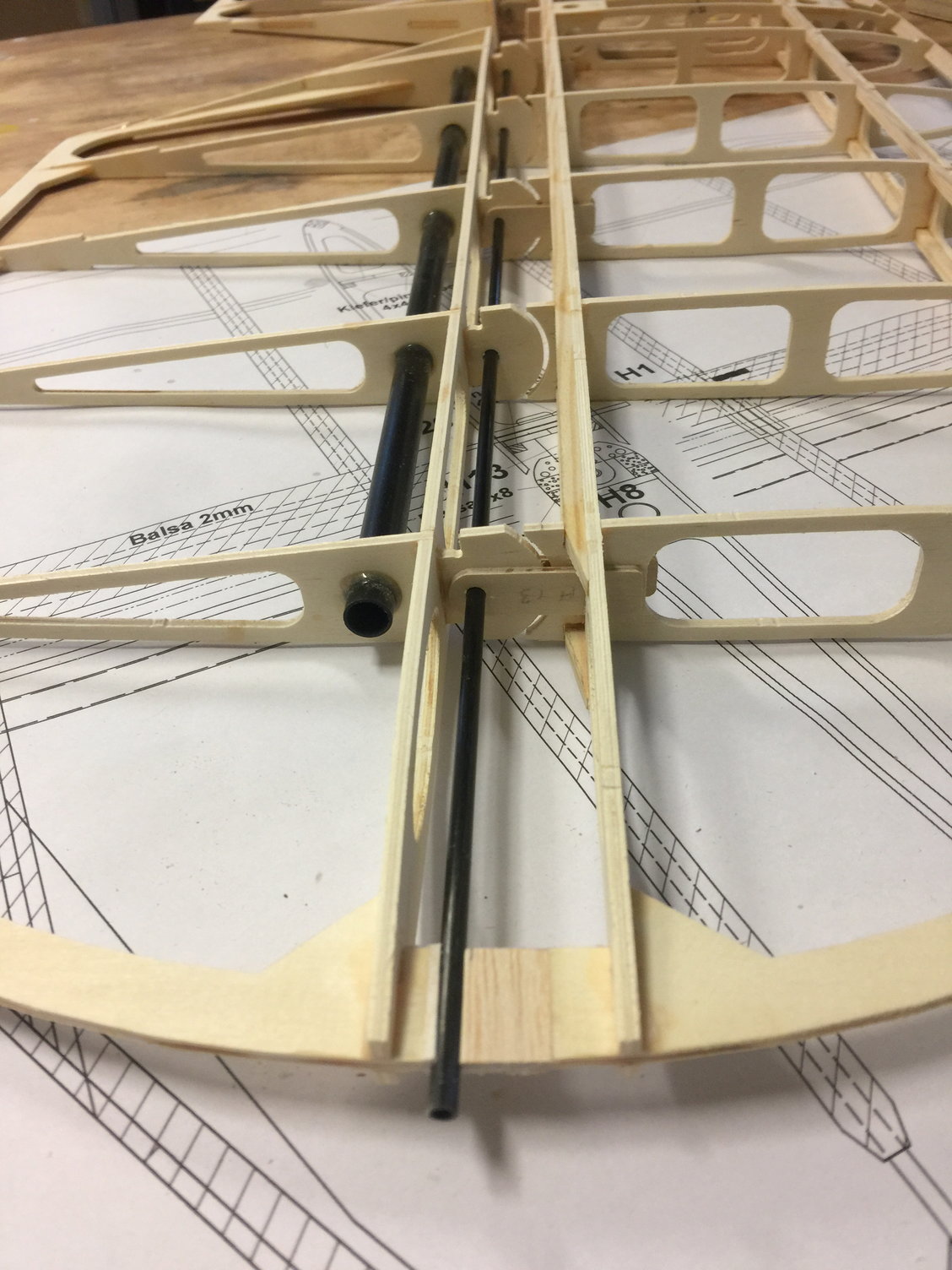
12-27-2021, 04:34 AM
#19
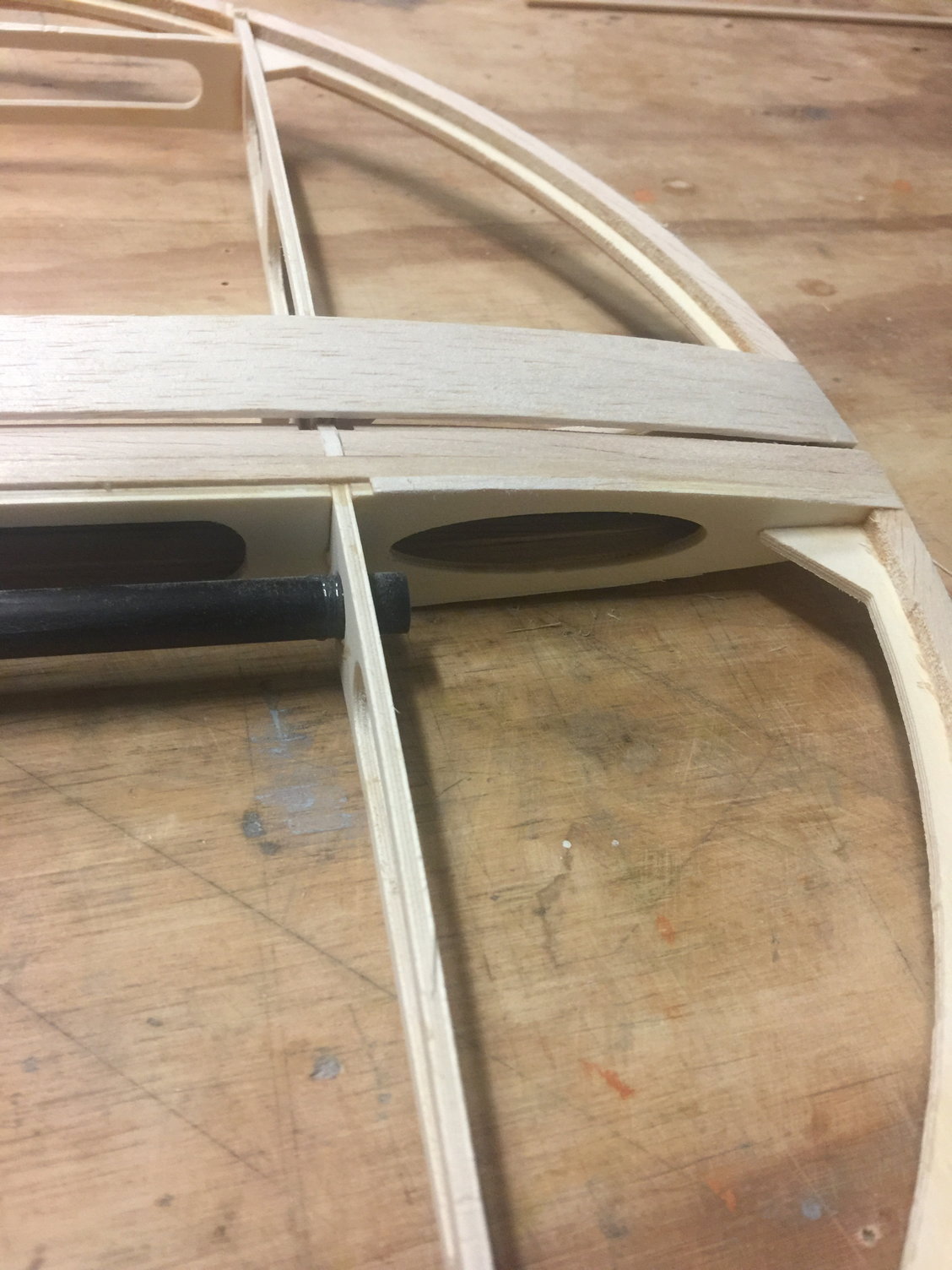
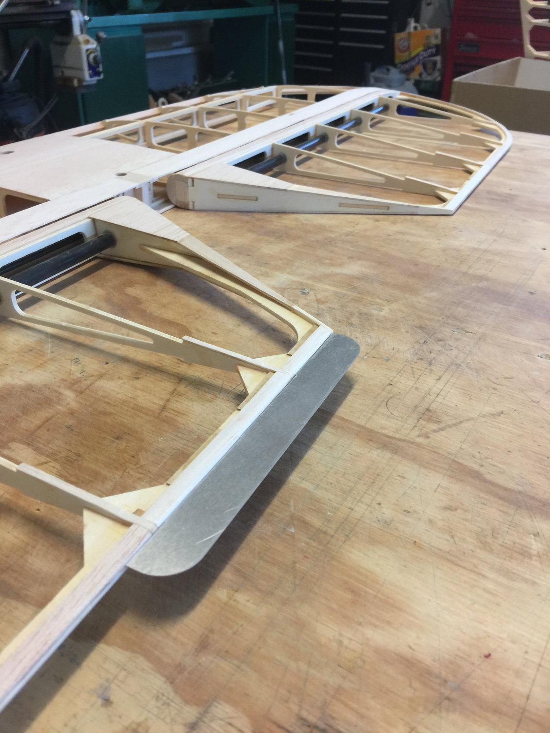
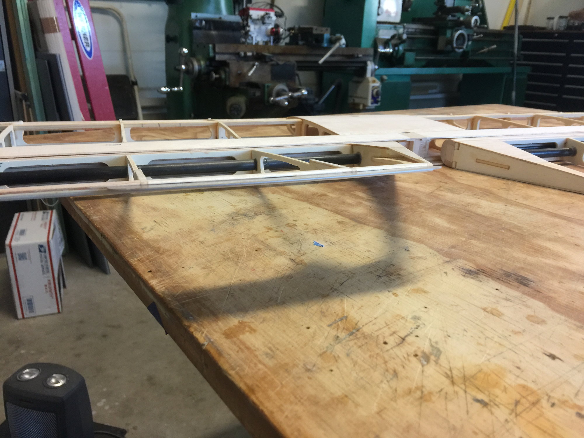
There was no way I was going to glue the aluminum tubes into the 4 wing panels. I just couldn't stand the thought of them sticking out of already huge wing panels. Since the flying wires take the bulk of the structural load we just need to hold the tubes in place. Pictures explain what I did. It's funny, the instructions call out the tube recepticals in the center sections AND the wing panels but obviously they simplified the design and removed them from the wing panels. I wish they hadn't. So this is what I did. I'll let the pictures explain.
The following users liked this post:
Steve (05-12-2022)
12-27-2021, 04:40 AM
#20
I'm going to just caption the pictures wherever possible from here out. Here is the horizontal stab:
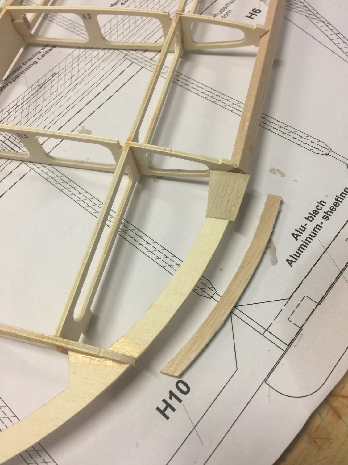
I did the leading edge terminations exactly like I did it on the main wings. Don't really understand how they wanted it otherwise! The piece I added is balsa for sanding ease. It works out great.
I did the leading edge terminations exactly like I did it on the main wings. Don't really understand how they wanted it otherwise! The piece I added is balsa for sanding ease. It works out great.
The following users liked this post:
Steve (05-12-2022)
12-27-2021, 04:53 AM
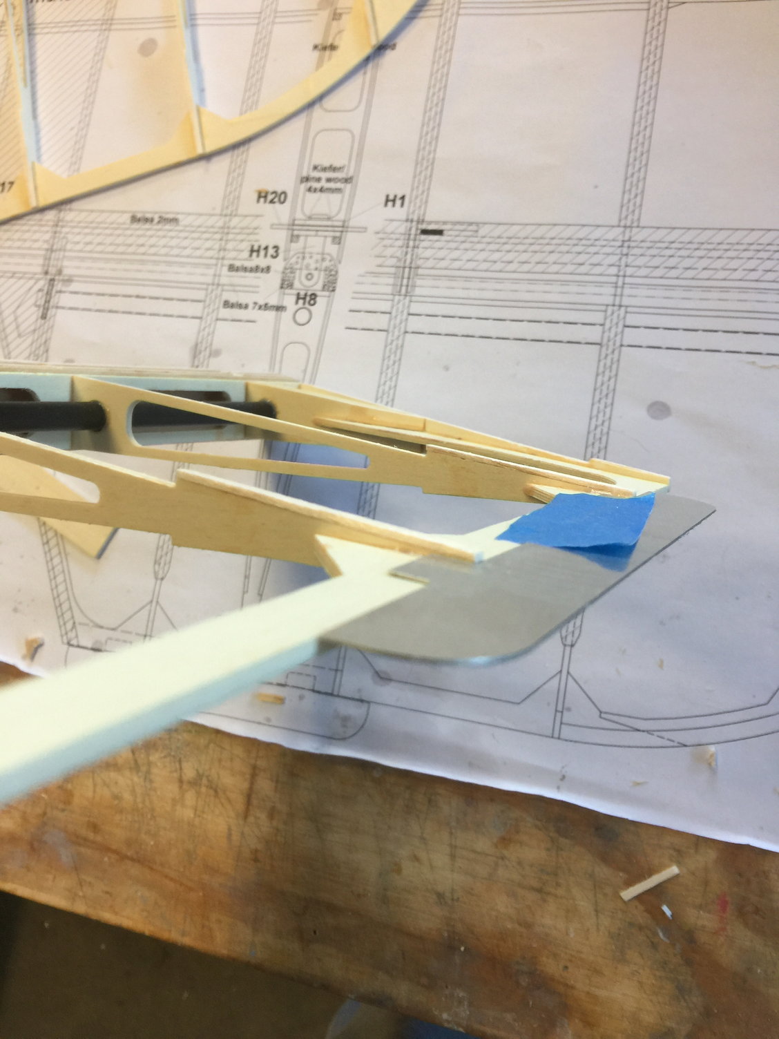
#21
Now the fun part. I spent hours trying to visualize everything that has to come together to make the stabilizer tips. The way I finally did it worked out great. But what a challenge:
First cut the tube channel
Put a balsa buffer on the elevator side.
Replace the ply piece on the stab side with balsa
Add balsa filler til the stab looks like this. Note: I sanded the balsa tip cap to receive the sheeting to come as you can see.
This is what the elevator side looks like. It's too complicated to even try to describe properly!
Zoom in and you begin to see how many little filler parts it took to get this crazy assembly to all work out. Good luck to you with yours. . .
When the balsa dust settled it had turned out magnificently.
The following users liked this post:
Steve (05-12-2022)
12-27-2021, 04:59 AM
#22
Now for the trim tab pockets
I biased the inboard end cap so that it was flush on the bottom and about 1.5mm on top to account for all the pocket space. In this pic you see the balsa caps I put on the rib ends, most of which will be sanded away to allow for the pockets
.8mm sheeting in place
Capped with balsa to create the pockets
12-28-2021, 05:20 AM
#23
It was a real brain teaser and a LOT of tedious work to get right but I'm very happy with the results.
EDIT: I've noted that I added balsa to the top rear of the elevator ribs to make room for the trim tab pockets (see pic). This process worked GREAT however it did require the use of thicker cap strips on the top elevator ribs for all the angles to work out. I used 3/32 balsa instead of the called for 2mm. Not a big difference but it makes everything turn out perfect.
So happy with this. Just fyi, I cut the 2-56 threaded part of a metal dobro clevis off and glued into the ends of all my hinge tubes. Now I just screw a rod into them to remove.
My hinge pocket method worked great.
If you don't have one of these power tools you are going to need one. The sander head saved me HOURS of work.
Last edited by mitchilito; 12-29-2021 at 01:55 AM.
12-29-2021, 07:13 AM
#24
Done! I did a rough calculation and realized I had over 20 hours of work on this stabilizer! I didn't see that coming.
Very happy with how it turned out.
EDIT: I think it's worth noting that I ran out of kit-supplied balsa a long time ago. I had some nice 1/16 in sheeting so I used that on everything on this stabilizer except the 3/32 cap strips on top. It worked out fine. Crazy they didn't provide nearly enough balsa to finish the kit!
Bottom
Top with trim tabs
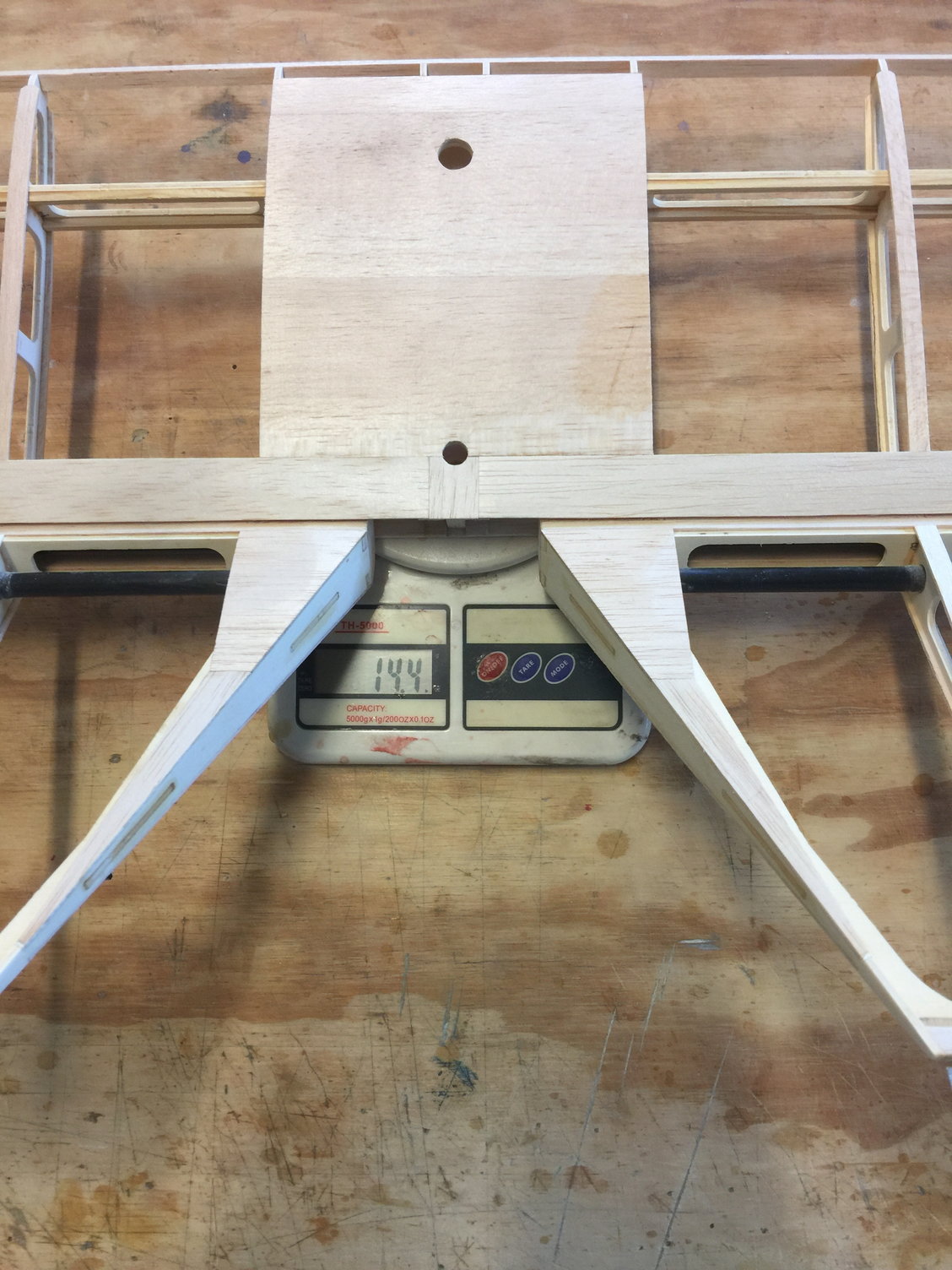
feels lighter than 14.4oz
Very happy with how it turned out.
EDIT: I think it's worth noting that I ran out of kit-supplied balsa a long time ago. I had some nice 1/16 in sheeting so I used that on everything on this stabilizer except the 3/32 cap strips on top. It worked out fine. Crazy they didn't provide nearly enough balsa to finish the kit!
Bottom
Top with trim tabs
feels lighter than 14.4oz
Last edited by mitchilito; 12-29-2021 at 07:21 AM.
The following users liked this post:
Steve (05-12-2022)
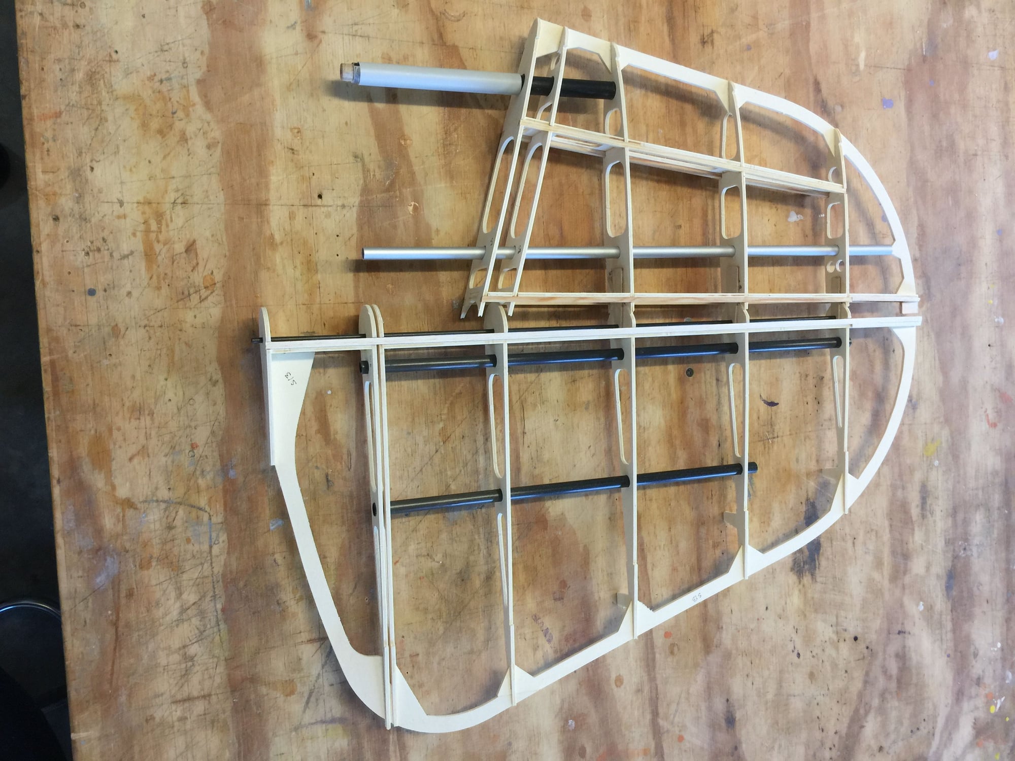
01-15-2022, 08:10 AM
#25
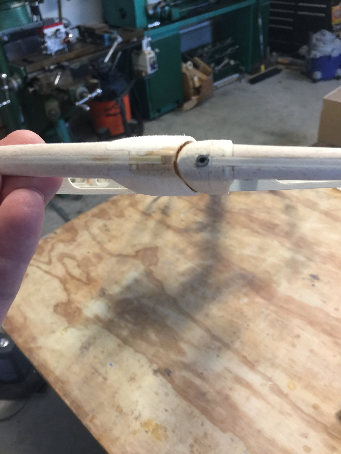
The vertical surfaces are pretty straight forward however, I thought the 14mm carbon tube and it's PVC receptical pipe were missing. I was looking for long pieces that would be cut to size so I thought they were missing (this kit has me gun shy!) but I accidentally located them in a hardware bag. - already cut to length, about 10 inches.
The following users liked this post:
Steve (05-12-2022)

