


battery/electrical setup question/s
 01-23-2011, 03:18 PM
#1
Senior Member
Thread Starter

Join Date: Mar 2010
Location: , WV
Posts: 900
Likes: 0
Received 0 Likes
on
0 Posts
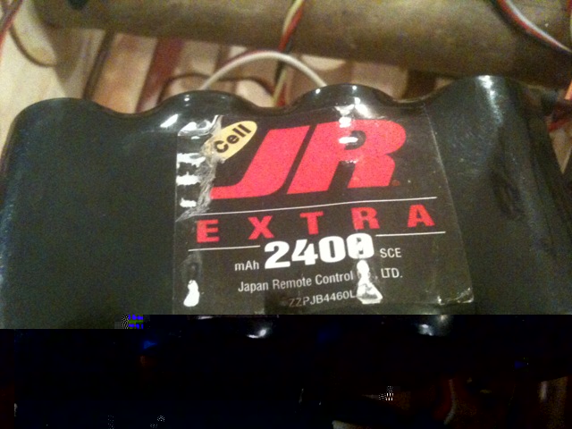
I recently purchased a used 30% Yak. It was complete minus RX and after looking iside the canopy Im a little confused.Im just getting into gassers with electronic ignitions...so what Im about to describemight be fine, but I just dont know so I thought Id post here to see opinions.There is only 1 battery and its a2400mAh 4.8 4cell JR pack ni-cad (there could have been another battery that was taken out before I bought the plane). There is a single switch,a UBEC and another separateboard device that I can only assume is some type of regulator. It has a 65cc EI engine.I can only assume that since there is only 1 on/off switch and battery pack on the plane...that the RX & servos are sharing the battery with the EI unit. The UBEC and other device is helping dedicate and control voltage to either or.I just recently built a 25% cub and I used 2 separate battery packs and switches so I could dedicate each its own power supply source. This, I thought was the preferred way. Now after seeing a much larger plane with this setup...well, makes me wonder.Ive tried to attach photos...but every time I do, it crashes. Besti can describe the devicethat is unknown, is that it is attached along with the UBEC and the on/off switch to the single battery.
Also, what is the best/preferred way to do a setup on a gas engine as far as flight pack / ignition pack...switches...other hardware...etcThanks for any and all responses.
Also, what is the best/preferred way to do a setup on a gas engine as far as flight pack / ignition pack...switches...other hardware...etcThanks for any and all responses.
 01-23-2011, 04:45 PM
#2

You always want to keep the ignition system components seperated as much as you can from the RC system. Never share the use of any of them. This applies to 2.4 radios as well. Can you post some pictures of what you have? Dan.
01-23-2011, 06:15 PM
#3
Senior Member
Thread Starter
Join Date: Mar 2010
Location: , WV
Posts: 900
Likes: 0
Received 0 Likes
on
0 Posts
Well, every timeI try to upload pics...my browser locks up and I have to close it to even see the forums again. I can try tomorrow from a different PC and see if that works, in the meantime I'll try and describe it better.
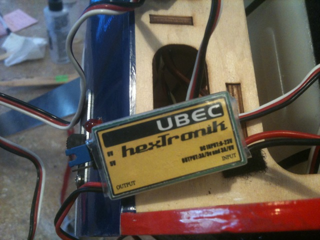
The UBEC is this one...
http://www.hobbyking.com/hobbyking/s...idproduct=3735#
I dunno what the other device is. Its a small circuit board with a capacitor on it and some SMT components. Looks like there are 3 -3wire leads on it like a Y (at first I thought it was a y w/servo reverser...but Im pretty sure thats not what it is as there is no adjuster pot anywhere on it. It is still connected up in the area with the UBEC and the power switch. I cant really tell what goes to where because of the way its routed and thought I would ask about it first before I started taking it all apart, although I may very well have to take it apart to understand it...we'll see.
My best guess is that it is some type of regulator or perhaps a "kill switch". I do know that there is an plug with IGNon it that was around all the other servo wires. Speaking of "kill switches"...what would you use on a 2 battery system to kill the ignition with the radio? Like I said...Im almost finished with my cub build and I have 2 batteries and switches but no way to kill the engine unless through the switch on the fuse.
The battery is this one...
http://www.rcplanet.com/JR_Extra_Rec...p/JRPB4460.htm
It was mounted in the rear of the plane and is quite heavy. This might explain a bit about why so much lead has been added to the firewall. But I do remember reading somewhere about a "12" rule...and thought that is probably why it is where it is. Does this 12" rule apply to 2.4 RX ? Or could I move the battery to try and help redistribute some weight and get rid of some dead weight.
01-23-2011, 07:31 PM
#4
Radio frequency interferenc(RFI) is a serious issue for any RF device. It applies to 2.4Gig just as well. Follow the safety guidlines of 12 inches or as much as you can get. For a 30% plane with about a 50cc motor, you can use a good set of NiCad batteries without using a regulator. That regulator is a complex part and will be a source of potential failure. Get yourself a name brand set of batteries. It sounds like the other device may be a kill switch. Smart-Fly makes a good one if you want to use it. I haven't been able to upload images for weeks. One of these days RCU will get back to normal. Dan.
01-24-2011, 04:53 AM
#5
Senior Member
Thread Starter
Join Date: Mar 2010
Location: , WV
Posts: 900
Likes: 0
Received 0 Likes
on
0 Posts
Thank you for your reply, and please excuse me for my ignorance on the subject. But thats why I wanted to ask all the questions now rather than later when its actually time to start flying (well its more of a matter of weather here in this part of the country more than anything).
I just uploaded the pics to my own webserver so I could show you them here now.
Here is the battery pack that was/is in the plane...
Here is the UBEC...
Here is the unknown device...
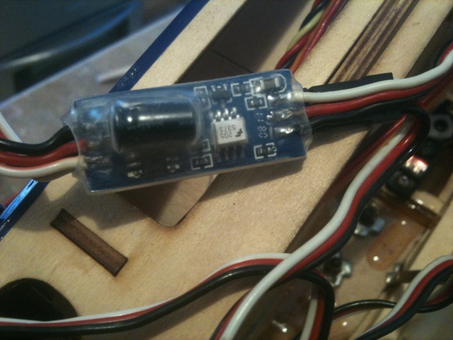
Hope the above image helps in figuring out exactly what that thing is. Problem is, the guy I purchased it from only owned it for a very short while before selling it to me. He never flew it or even took the canopy off to look inside. He bought it strictly to resale. So he doesnt know anything about it.
Thanks again.
I just uploaded the pics to my own webserver so I could show you them here now.
Here is the battery pack that was/is in the plane...
Here is the UBEC...
Here is the unknown device...
Hope the above image helps in figuring out exactly what that thing is. Problem is, the guy I purchased it from only owned it for a very short while before selling it to me. He never flew it or even took the canopy off to look inside. He bought it strictly to resale. So he doesnt know anything about it.
Thanks again.
01-24-2011, 07:49 AM
#6
Here's the website for UBEC
http://www.koolflightsystems.com/ultimatebec.htm
It's obviuos what the battery is.
I don't know what the other module is. It may be a battery regulator.
Is the plane electric powered? Dan.
http://www.koolflightsystems.com/ultimatebec.htm
It's obviuos what the battery is.
I don't know what the other module is. It may be a battery regulator.
Is the plane electric powered? Dan.
01-24-2011, 10:31 AM
#7
Senior Member
Thread Starter
Join Date: Mar 2010
Location: , WV
Posts: 900
Likes: 0
Received 0 Likes
on
0 Posts
ORIGINAL: DAN REISS
Here's the website for UBEC
http://www.koolflightsystems.com/ultimatebec.htm
It's obviuos what the battery is.
I don't know what the other module is. It may be a battery regulator.
Is the plane electric powered? Dan.
Here's the website for UBEC
http://www.koolflightsystems.com/ultimatebec.htm
It's obviuos what the battery is.
I don't know what the other module is. It may be a battery regulator.
Is the plane electric powered? Dan.
Yeah...I also found the UBEC on HK. Low cost deal at only 7 bux.
The batt...well Ive never had any issues with any JR packs Ive used in the past...soI can only assume its a decent pack.
No...this is a gasser. It has a 65cc RCGF engine. Here are a couple more pics I took simply because I couldnt believe the amount of weight added to the firewall.
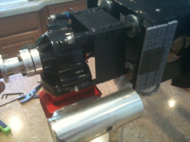
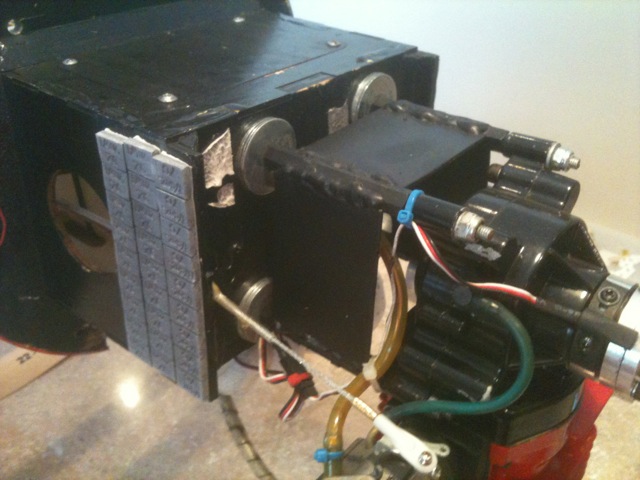
Also...the engine mount/standoffs is obviously home-made out of some long nuts and metal welded together. One can only imagine the weight of that thing...not even counting the added lead.
I dont have a scale other than bathroom digitals. I weighed myself...then weighed myself holding the plane with wings on it and it come in at 18lbs. With a 65cc engine on this plane (calls for 40-50cc) I would have thought it would have been nose heavy.
Anyway...perhaps you could point me to some reading on the best way to set up a 2 battery system (not for redundancy...but to isolate RX &IGN). And some type of kill switch that can control the IGNpower from the radio. The way I have my cub right now, the only way I can kill the IGN is if its on the ground and I can flip the switch. Id prefer to be able to kill the IGN while in air if the need was there, ie broken throttle servo.
Thanks for your help.
01-24-2011, 11:38 AM
#8
I don't know why the battery was mounted at the rear of the plane and that there is also weight up front. The two contradict each other. Those standoffs look very long, about 3 inches. They should be as short as possible to keep the vibration to a minimum and not but excess forces on the engine lugs. Get some commercially available ones that are more sturdy or add a motor box in front of the firewall. Once again, keep all the ignition componets seperate from the RC components. That includes the batteries, switches, wires, servos. receiver, antenna and anything else i haven't put down. Don't use a metall throttle push rod either. Don't use that battery until you know it's good. You will need a battery cycler to determine it's health and capacity. If you can't determine that it's good, assume it's bad and replace it. Go to smart-fly.com and get one of their optical kill switches. Dan.
01-24-2011, 12:24 PM
#9
Senior Member
Thread Starter
Join Date: Mar 2010
Location: , WV
Posts: 900
Likes: 0
Received 0 Likes
on
0 Posts
Thanks Dan for your info on the matter. It is much appreciated.
I am sure that I will be working this plane, or should I say re-working it quite a bit because at the very least...its not how I would have done it if I had been the one to put it together.
The standoffs (if one would even call those fabbed up things) are quite long...and you are probably close in your guess as to them being 3" in length. The position of the engine could be where it needs to be as the cowl fits nicely, but of course looks can be decieving. I have contacted the distributor about getting a manual and hopefully there will be the measurement of firewall to prop hub so I can rest assured that the motor is hanging in roughly the right spot. If not, then I'll have a lot more work to do as the muffler barely clears the firewall now!
All of your tips regarding electrical component placement will not fall on deaf ears. Ive witnessed a couple of these 30% planes crash and its not something I want to ever lose control of, thats for sure. So will do everything in my ability to make it as safe as possible.
Im gonna go check out the opti kill. I hope it will work with the way I have started the build on my cub. I had no idea that these were available and already installed 2 manual switches in the cubs fuse. Can you still use a mechanical on/off switch on the fuse with the opti kill?
Thanks
01-24-2011, 01:14 PM
#10
ORIGINAL: ATVAlliance
Yeah...I also found the UBEC on HK. Low cost deal at only 7 bux.
The batt...well Ive never had any issues with any JR packs Ive used in the past...soI can only assume its a decent pack.
No...this is a gasser. It has a 65cc RCGF engine. Here are a couple more pics I took simply because I couldnt believe the amount of weight added to the firewall.
Also...the engine mount/standoffs is obviously home-made out of some long nuts and metal welded together. One can only imagine the weight of that thing...not even counting the added lead.
I dont have a scale other than bathroom digitals. I weighed myself...then weighed myself holding the plane with wings on it and it come in at 18lbs. With a 65cc engine on this plane (calls for 40-50cc) I would have thought it would have been nose heavy.
Anyway...perhaps you could point me to some reading on the best way to set up a 2 battery system (not for redundancy...but to isolate RX &IGN). And some type of kill switch that can control the IGNpower from the radio. The way I have my cub right now, the only way I can kill the IGN is if its on the ground and I can flip the switch. Id prefer to be able to kill the IGN while in air if the need was there, ie broken throttle servo.
Thanks for your help.
ORIGINAL: DAN REISS
Here's the website for UBEC
http://www.koolflightsystems.com/ultimatebec.htm
It's obviuos what the battery is.
I don't know what the other module is. It may be a battery regulator.
Is the plane electric powered? Dan.
Here's the website for UBEC
http://www.koolflightsystems.com/ultimatebec.htm
It's obviuos what the battery is.
I don't know what the other module is. It may be a battery regulator.
Is the plane electric powered? Dan.
Yeah...I also found the UBEC on HK. Low cost deal at only 7 bux.
The batt...well Ive never had any issues with any JR packs Ive used in the past...soI can only assume its a decent pack.
No...this is a gasser. It has a 65cc RCGF engine. Here are a couple more pics I took simply because I couldnt believe the amount of weight added to the firewall.
Also...the engine mount/standoffs is obviously home-made out of some long nuts and metal welded together. One can only imagine the weight of that thing...not even counting the added lead.
I dont have a scale other than bathroom digitals. I weighed myself...then weighed myself holding the plane with wings on it and it come in at 18lbs. With a 65cc engine on this plane (calls for 40-50cc) I would have thought it would have been nose heavy.
Anyway...perhaps you could point me to some reading on the best way to set up a 2 battery system (not for redundancy...but to isolate RX &IGN). And some type of kill switch that can control the IGNpower from the radio. The way I have my cub right now, the only way I can kill the IGN is if its on the ground and I can flip the switch. Id prefer to be able to kill the IGN while in air if the need was there, ie broken throttle servo.
Thanks for your help.
01-24-2011, 03:25 PM
#13

ORIGINAL: Taildragger726
Wonder why the BEC is in there?
Wonder why the BEC is in there?
My guess is that it was being set up for some other flight battery and the seller took it out and laid the large JR battery inside and it bounced back to the rear during handling. Such a theory explains why the BEC and why the battery was aft while all the weight was added to the nose.
Most EI units need a 900-1100 mah 4 cell pack. If your cautious and have a history of being attentive to your batteries, one flight battery is fine plus an ignition battery. A four cell pack of that size is ok for a larger plane unless your using 2.4 and if so, a five cell pack has been deemed the standard because of brown outing of the receiver when a lot of servo action takes place. If you don't cycle or watch your batteries carefully, then a dual battery system is a wise choice.
I agree with others when they warn not to assume the JR battery is ok. My history with JR batteries is not as good as yours and I use JR stuff exclusively. It is important to cycle it and prove it's at least 70% of capacity.
01-25-2011, 06:04 AM
#14
Senior Member
Thread Starter
Join Date: Mar 2010
Location: , WV
Posts: 900
Likes: 0
Received 0 Likes
on
0 Posts
ORIGINAL: Tony Hallo</p>
Looks like the throttle cable could be steel, if so I would eliminate it and use a non conducting product
ORIGINAL: ATVAlliance</p>
</p>
Yeah...I also found the UBEC on HK. Low cost deal at only 7 bux.
The batt...well Ive never had any issues with any JR packs Ive used in the past...so I can only assume its a decent pack.</p>
No...this is a gasser. It has a 65cc RCGF engine. Here are a couple more pics I took simply because I couldnt believe the amount of weight added to the firewall.</p>
</p>
</p>
Also...the engine mount/standoffs is obviously home-made out of some long nuts and metal welded together. One can only imagine the weight of that thing...not even counting the added lead.</p>
I dont have a scale other than bathroom digitals. I weighed myself...then weighed myself holding the plane with wings on it and it come in at 18lbs. With a 65cc engine on this plane (calls for 40-50cc) I would have thought it would have been nose heavy.</p>
Anyway...perhaps you could point me to some reading on the best way to set up a 2 battery system (not for redundancy...but to isolate RX & IGN). And some type of kill switch that can control the IGN power from the radio. The way I have my cub right now, the only way I can kill the IGN is if its on the ground and I can flip the switch. Id prefer to be able to kill the IGN while in air if the need was there, ie broken throttle servo.</p>
Thanks for your help.
ORIGINAL: DAN REISS</p>
Here's the website for UBEC
http://www.koolflightsystems.com/ultimatebec.htm</p>
It's obviuos what the battery is.</p>
I don't know what the other module is. It may be a battery regulator.</p>
Is the plane electric powered? Dan.</p>
Here's the website for UBEC
http://www.koolflightsystems.com/ultimatebec.htm</p>
It's obviuos what the battery is.</p>
I don't know what the other module is. It may be a battery regulator.</p>
Is the plane electric powered? Dan.</p>
Yeah...I also found the UBEC on HK. Low cost deal at only 7 bux.
The batt...well Ive never had any issues with any JR packs Ive used in the past...so I can only assume its a decent pack.</p>
No...this is a gasser. It has a 65cc RCGF engine. Here are a couple more pics I took simply because I couldnt believe the amount of weight added to the firewall.</p>
</p>
</p>
Also...the engine mount/standoffs is obviously home-made out of some long nuts and metal welded together. One can only imagine the weight of that thing...not even counting the added lead.</p>
I dont have a scale other than bathroom digitals. I weighed myself...then weighed myself holding the plane with wings on it and it come in at 18lbs. With a 65cc engine on this plane (calls for 40-50cc) I would have thought it would have been nose heavy.</p>
Anyway...perhaps you could point me to some reading on the best way to set up a 2 battery system (not for redundancy...but to isolate RX & IGN). And some type of kill switch that can control the IGN power from the radio. The way I have my cub right now, the only way I can kill the IGN is if its on the ground and I can flip the switch. Id prefer to be able to kill the IGN while in air if the need was there, ie broken throttle servo.</p>
Thanks for your help.
The throttle cable is just that, cable. It runs inside of a plastic sheething, a lot like a control rod tube/guide. the end is secured to the carb with a plasic ball link.</p>
With this being the case...is it ok, or should I replace it. If I should replace it...with what? Thanks</p>
</p>
</p>
ORIGINAL: DAN REISS</p>
The kill switches have to be optical. The mechanical ones will couple the ignition interference right into the receiver. The optical line prevents this. It looks like you have a lot of work to do. Keep us posted. Dan.
The kill switches have to be optical. The mechanical ones will couple the ignition interference right into the receiver. The optical line prevents this. It looks like you have a lot of work to do. Keep us posted. Dan.
I went to the site in the link you provided and looked at the opti-kill. I think I will definitely buy these for this plane (as well as my other 2 gassers i am working on) because I will definitely be going with separate batts for RX and IGN.</p>
</p>
ORIGINAL: AA5BY</p>
Me too?</p>
My guess is that it was being set up for some other flight battery and the seller took it out and laid the large JR battery inside and it bounced back to the rear during handling. Such a theory explains why the BEC and why the battery was aft while all the weight was added to the nose.</p>
Most EI units need a 900-1100 mah 4 cell pack. If your cautious and have a history of being attentive to your batteries, one flight battery is fine plus an ignition battery. A four cell pack of that size is ok for a larger plane unless your using 2.4 and if so, a five cell pack has been deemed the standard because of brown outing of the receiver when a lot of servo action takes place. If you don't cycle or watch your batteries carefully, then a dual battery system is a wise choice.</p>
I agree with others when they warn not to assume the JR battery is ok. My history with JR batteries is not as good as yours and I use JR stuff exclusively. It is important to cycle it and prove it's at least 70% of capacity.
ORIGINAL: Taildragger726</p>
Wonder why the BEC is in there?
Wonder why the BEC is in there?
My guess is that it was being set up for some other flight battery and the seller took it out and laid the large JR battery inside and it bounced back to the rear during handling. Such a theory explains why the BEC and why the battery was aft while all the weight was added to the nose.</p>
Most EI units need a 900-1100 mah 4 cell pack. If your cautious and have a history of being attentive to your batteries, one flight battery is fine plus an ignition battery. A four cell pack of that size is ok for a larger plane unless your using 2.4 and if so, a five cell pack has been deemed the standard because of brown outing of the receiver when a lot of servo action takes place. If you don't cycle or watch your batteries carefully, then a dual battery system is a wise choice.</p>
I agree with others when they warn not to assume the JR battery is ok. My history with JR batteries is not as good as yours and I use JR stuff exclusively. It is important to cycle it and prove it's at least 70% of capacity.
I really had no idea why either. I could understand if it was an electric motor powered plane...but with a gasser, I was sort of confused...thus one of the the reasons for the thread.</p>
As far as teh battery being in the rear of the fuse. It did not just end up back there. It was actually zip tied to a former in the back of the fuse. I had to cut the zip ties to remove it for the picture. Looks like that is where it has always been.</p>
Funny thing to me is that there is a hatch on top of the motor mount box on the firewall that would be an ideal place for the battery/ies. And going with 2 LiFe batts placed inside there...there would have been no need for that much lead added to the front of the plane, if any at all.</p>
Like someone already said above...looks like I have a lot of work to do. Just want to make sure that I do it right.</p>
This weekend I will try and get the plane back out of my trailer and inside and carefully take this electrical system apart plug at a time and will draw a diagram as to the way it is wired. I'll update this thread when I do that. This should take all the guess work out as to what way it "could" be working.</p>
Thanks again for everyones input. Much appreciated!</p>
01-25-2011, 04:27 PM
#16
Senior Member

Join Date: Jan 2004
Location: N Ft Myers,
FL
Posts: 1,232
Likes: 0
Received 0 Likes
on
0 Posts
Uh, I've used metal and carbon push rods for the throttle, also powered the ignition from the same battery as the receiver pack with no ill effects. Done this for over two years! Using JR 2.4 stuff, DA and DLE ignitions.
Your choice, Old school or New school.
Your choice, Old school or New school.
01-26-2011, 05:54 AM
#17
Senior Member
Thread Starter
Join Date: Mar 2010
Location: , WV
Posts: 900
Likes: 0
Received 0 Likes
on
0 Posts
One thing I got to thinking about the UBEC. Is it probably was put in line as a failsafe for the RX. The UBEC would make sure there was an even flow of power for the RX and in the event the main batt died...there should be enough power left from the UBEC to power the servos for a dead stick??? At least thats an option, right?
I was under the impression that the only concern with metal to for the throttle linkage was IF there was a chance that the rod had any chance of vibrating against another piece of metal, ie the engine block.
The way this one is connected...I am pretty certain, almost 100% certain that the metal cable could never come into contact with anything else metal to create any interference. But I will double check it to be sure.
Im sure what you say is fact. As this plane obviously has been flown this way probably since it was built. But based on what I had been reading, when I started the build on my 1/4 scale Cub last month...I decided to go with 2 batteries just to be on the safe side. Afterall, it doesnt cost that much more these days with the LiFe batts on the mkt.
Again, thanks for everyones input. I'll ltry and update this thread with a diagram of the wiring this weekend if I can. Its the wifes b-day, so I may or may not have the time.
ORIGINAL: DAN REISS
The throttle pushrod has to be a nonconductive material to avoid any potential interference from the ignition. Dan.
The throttle pushrod has to be a nonconductive material to avoid any potential interference from the ignition. Dan.
I was under the impression that the only concern with metal to for the throttle linkage was IF there was a chance that the rod had any chance of vibrating against another piece of metal, ie the engine block.
The way this one is connected...I am pretty certain, almost 100% certain that the metal cable could never come into contact with anything else metal to create any interference. But I will double check it to be sure.
ORIGINAL: Taildragger726
Uh, I've used metal and carbon push rods for the throttle, also powered the ignition from the same battery as the receiver pack with no ill effects. Done this for over two years! Using JR 2.4 stuff, DA and DLE ignitions.
Your choice, Old school or New school.
Uh, I've used metal and carbon push rods for the throttle, also powered the ignition from the same battery as the receiver pack with no ill effects. Done this for over two years! Using JR 2.4 stuff, DA and DLE ignitions.
Your choice, Old school or New school.
Again, thanks for everyones input. I'll ltry and update this thread with a diagram of the wiring this weekend if I can. Its the wifes b-day, so I may or may not have the time.
01-26-2011, 08:16 AM
#18
That metallic throttle cable acts like an antenna as it passes through the RF field that exists around the igniton module, battery, switch and the motor. It will bring that RF right into the servo and hence the receiver. It doesn't happen all the time but just enough to result in a crash every now and then. It makes no difference if it is making metallic contact with the engine or not. It works just like the antenna receiver. Use a non metallic pushrod to be on the safe side.
01-27-2011, 07:52 AM
#19
Senior Member
Thread Starter
Join Date: Mar 2010
Location: , WV
Posts: 900
Likes: 0
Received 0 Likes
on
0 Posts
This is what I have now...or something very similar

But you are saying I need something like the Gold n Rod deal?

But you are saying I need something like the Gold n Rod deal?
01-28-2011, 05:44 AM
#21
Senior Member
Thread Starter
Join Date: Mar 2010
Location: , WV
Posts: 900
Likes: 0
Received 0 Likes
on
0 Posts
Looks like the upload worked.
Thanks for all of the pics. I will start collecting all of the things needed to get this Yak set up right!
Still, will try this weekend to draw a diagram of the current wiring setup and post back here with it.
Thanks for all of the pics. I will start collecting all of the things needed to get this Yak set up right!
Still, will try this weekend to draw a diagram of the current wiring setup and post back here with it.
02-26-2011, 08:30 PM
#22
Senior Member
Thread Starter
Join Date: Mar 2010
Location: , WV
Posts: 900
Likes: 0
Received 0 Likes
on
0 Posts
For the first time since I last posted, I was able to get the Yak out of the trailer and take a more up close look at the wiring. I drew a crude diagram and will attach to this post (hopefully will be able to anyway).
Was/Is this type of setup acceptable? Ive always thought it best to have 2 separate batteries, 1 each for ignition and RX unit.
Was/Is this type of setup acceptable? Ive always thought it best to have 2 separate batteries, 1 each for ignition and RX unit.
02-26-2011, 09:08 PM
#23
That is extremely bad. You have all the parts of the ignition system and everything that is part of the radio completely isolated from each other. That is both physically and electrical. Do your best to get them this way. Dan.
02-27-2011, 08:43 AM
#24
Senior Member
My Feedback: (14)
Dont take this wrong please, trying to help, dont combine the power supplies before the the rx! you put the full reliance of the planes needs on that one switch.
run a single batt with dual outputs and dual fail safe switches before your posted setup.....switch failure seems to be the biggest cause of problems.
Keep the ignition totally separate. give it its own batt and switch. I am almost willing to bet that bat in your plane was the old ign. batt and the guy was running lipos for the rx's, hence the BEC. They make IBEC's (ignition battery eliminator circuit)now, but i do not trust em yet. The electrical link between systems has to be there even if filtered.thats your call but i advise against it. A optically isolated kill switch is the way to go IMO. I use the rcxl switch, it has a led you mount in the fuse to tell you when it is armed also. I set the the failsafe to go to idle and the kill to stay running in mine, just incase it comes back and i can save it. if the battery(s) have came unplugged in flight somehow the kill switch will shut it down tho.
On the batts i run two, into thier own switches and to the rx. just plug the extra power lead in any unused port. dual batts can create a problem when charging, the common ground. I unplug one batt so they charge totally separate. run 6volt, alot of 2.4 gig systems will not tolerate low voltage at all they go into brown out and you will lose control till it reboots. high draw servos we use in these things can and will do just that to ya.
Are the rudder and ele servos in the tail of your plane? if not i think i would move em there and see how much of the lead you could pull. motor mount looks plenty stout also. every once you can pull from the tail should take 3 or so off the nose.
02-27-2011, 04:24 PM
#25
Senior Member
Thread Starter
Join Date: Mar 2010
Location: , WV
Posts: 900
Likes: 0
Received 0 Likes
on
0 Posts
The above diagram is how the wiring was done when I got it (and still is that way). I havent touched it...other than to take the battery out. I found it odd as it only had 1 battery and all of the gassers I have seen have always had two, one for each ignition module and rx unit. But there were no other places for a 2nd battery to plug in and looking at the wiring, the original builder/owner decided to do it this way and run 1 large battery pack.
Again, I didnt think it was the best practice...thus my post. And am grateful for all of the replies in describing as to why its not the best practice. I'll make sure to make the appropriate changes.
As far as servos...both of the elevator servos are side mounted at the tail and the elevator servo is inside behind the CG but not all the way back.
There is a battery compartment inside the firewall box that the original builder did not utillze. I feel with running a 2 battery IGN/RX system and putting them both there...will allow me to remove most, if not all of the weight from the firewall. I may or may not redo the engine mount. Although it is very crude...it definitely is strong and I am not concerned it would fail. IF I were to replace it, it would be because I needed to shed weight for balancing.
PS...I made a typo on the graphic...it should read 4cell 4.8v battery pack. Sorry.

