


TF Cessna 182 - That Lateral Fuel Tank...
 07-10-2020, 11:28 PM
#1

The lateral installation of the fuel tank has bothered me ever since I first saw the plans. I just couldn’t reassure myself it would provide a reliable fuel supply towards the end of the flight and I really would rather not have a dead stick on the landing approach.
While I understand the motivation to keep the cockpit free of model stuff so it could be detailed nicely, this cannot be at the expense of reliable fuel supply.
So I took a closer look at the design and devised this solution.
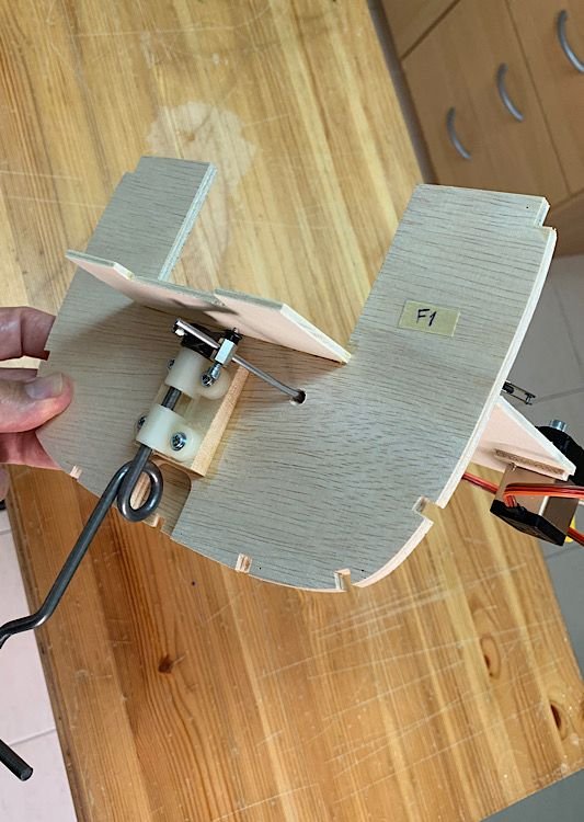
The engine I noticed, was designed to fit the mount at its extreme front end. I saw no reason for that. The firewall and mount can easily be brought forward such that with a longitudinal tank, the tank would not protrude into the cockpit , as with the lateral tank design.
This would only require lengthening the engine box to compensate for installing the engine further back on the mount.
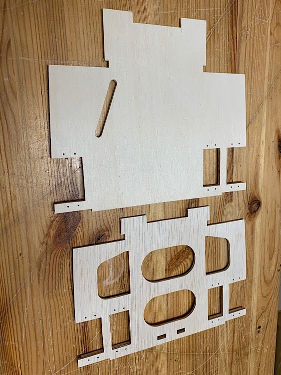
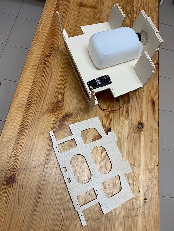
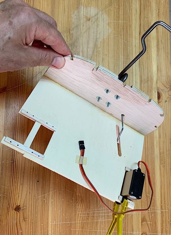
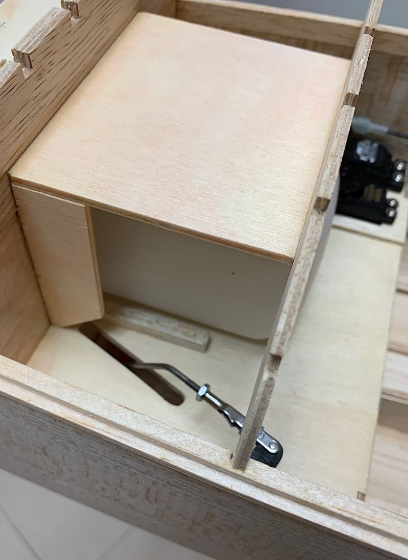
So I moved the firewall 27 mm forward. Obviously I had to make a new servo & tank mounting plate to allow the modification. This was actually welcome since I didn’t like the massive lightening holes in the original which made it rather flimsy. I appreciate lightening holes were possible, but in front of the CG? In a primary structural part?
Anyway pics attached for anyone else considering a simple modification. More parts will be lengthened later around the engine box but it’s simple.
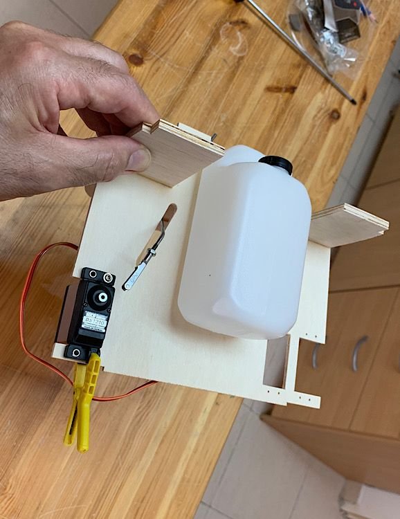
BTW I try to accomplish as much as possible detail and sub assembly work prior to construction.
While I understand the motivation to keep the cockpit free of model stuff so it could be detailed nicely, this cannot be at the expense of reliable fuel supply.
So I took a closer look at the design and devised this solution.
The engine I noticed, was designed to fit the mount at its extreme front end. I saw no reason for that. The firewall and mount can easily be brought forward such that with a longitudinal tank, the tank would not protrude into the cockpit , as with the lateral tank design.
This would only require lengthening the engine box to compensate for installing the engine further back on the mount.
So I moved the firewall 27 mm forward. Obviously I had to make a new servo & tank mounting plate to allow the modification. This was actually welcome since I didn’t like the massive lightening holes in the original which made it rather flimsy. I appreciate lightening holes were possible, but in front of the CG? In a primary structural part?
Anyway pics attached for anyone else considering a simple modification. More parts will be lengthened later around the engine box but it’s simple.
BTW I try to accomplish as much as possible detail and sub assembly work prior to construction.


 07-18-2020, 04:12 AM
#3
Thanks David.
This is my first TF kit and I’m generally very happy with it, apart from the tank installation and lack of mention that you need to ‘twist’ the ailerons to follow the washout, but thanks to my scratch building experience I have easily resolved all (including some improvements to the construction process in the manual)
This is my first TF kit and I’m generally very happy with it, apart from the tank installation and lack of mention that you need to ‘twist’ the ailerons to follow the washout, but thanks to my scratch building experience I have easily resolved all (including some improvements to the construction process in the manual)
11-26-2020, 10:31 PM
#4
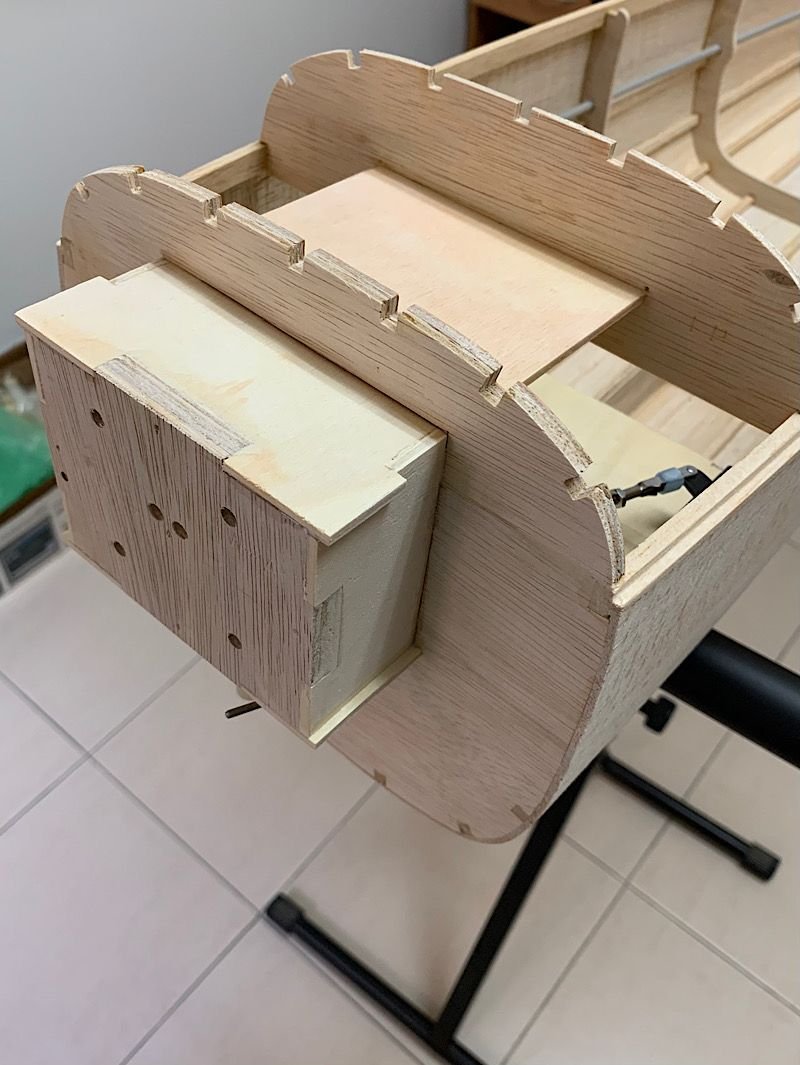
All done.
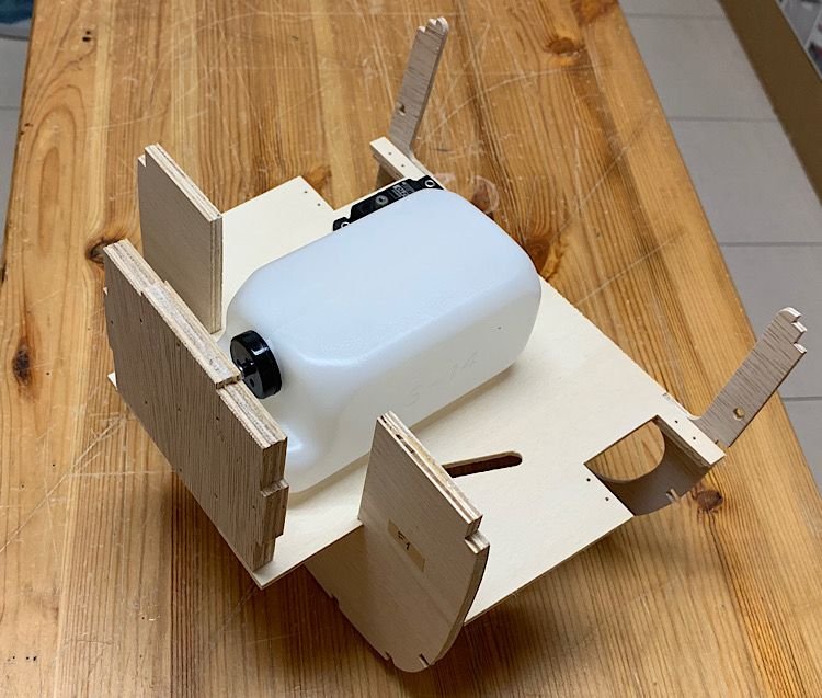
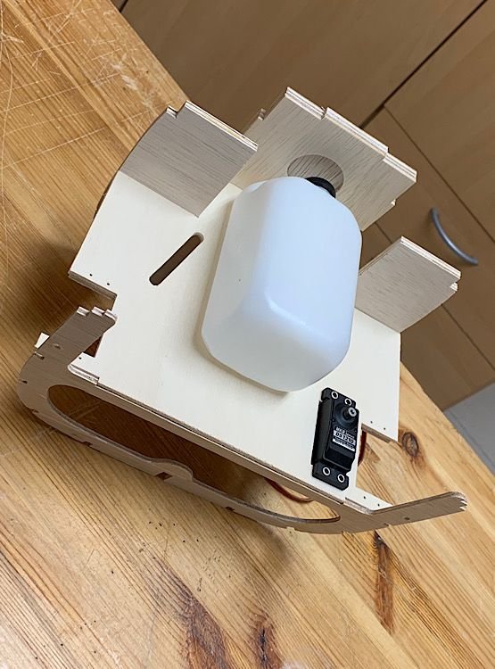
Although the plan shows a 12oz tank, I got this 14oz tank aligned in the conventional orientation without protruding back beyond the instrument panel.
Still ample room for the engine and mount.
Gives me peace of mind regarding fuel delivery to the engine...
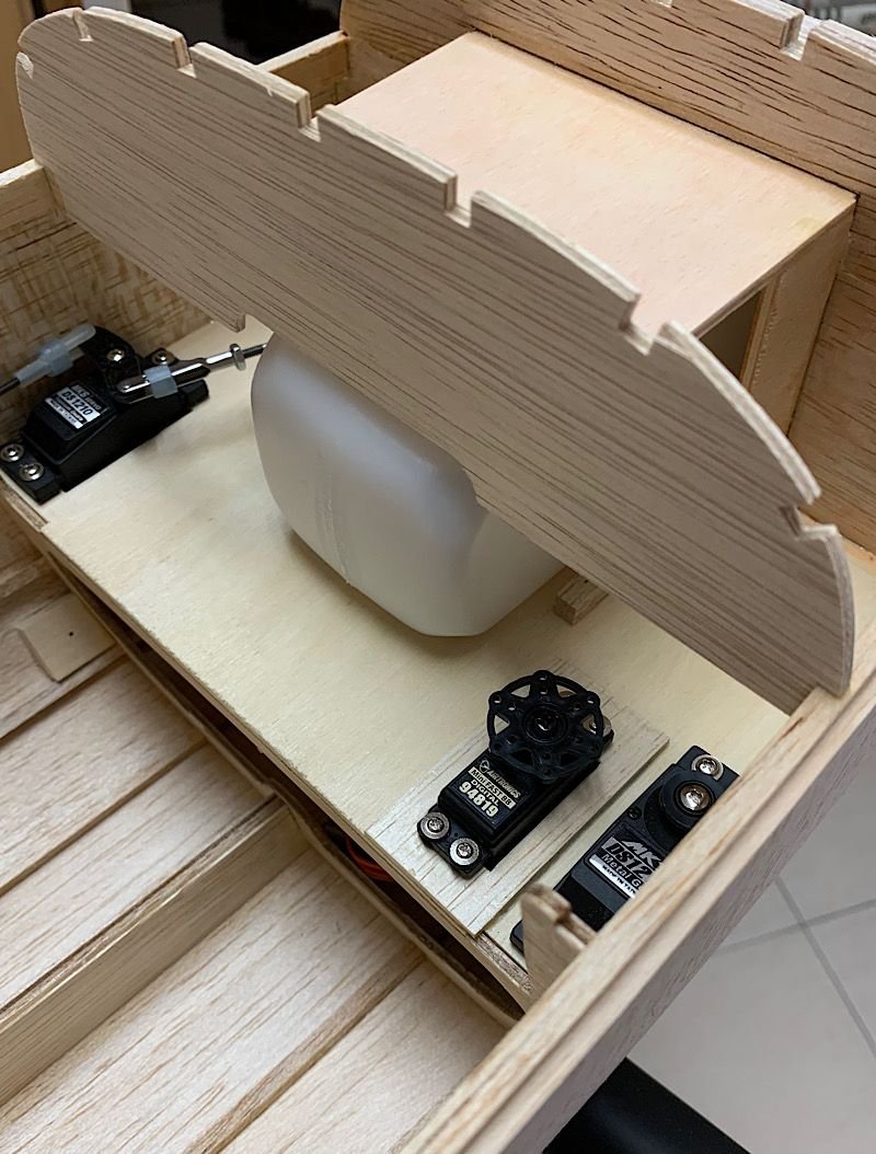
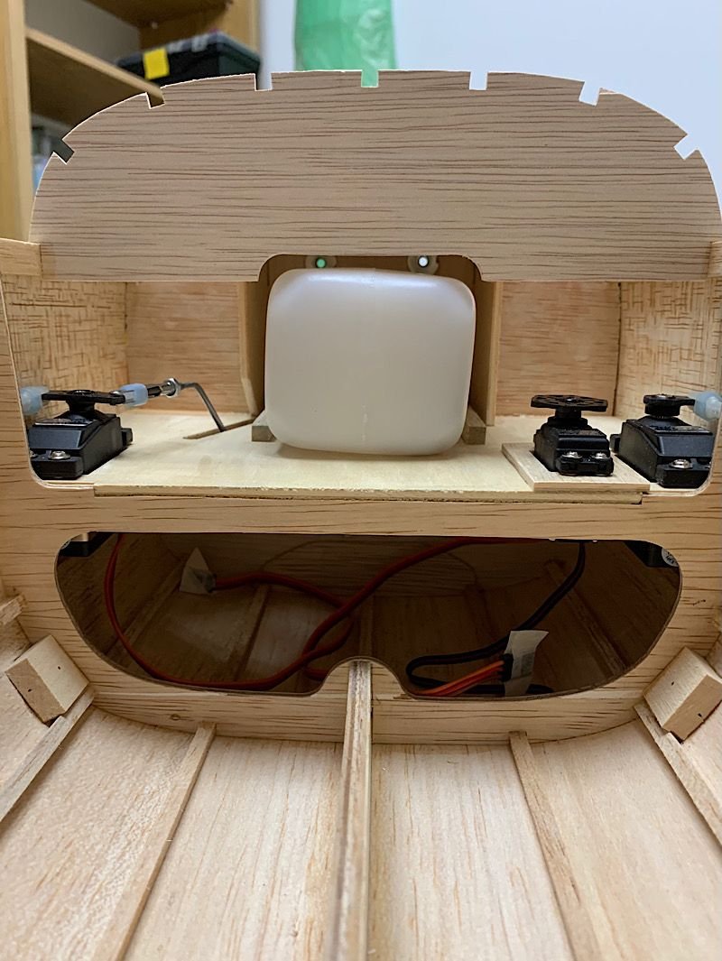
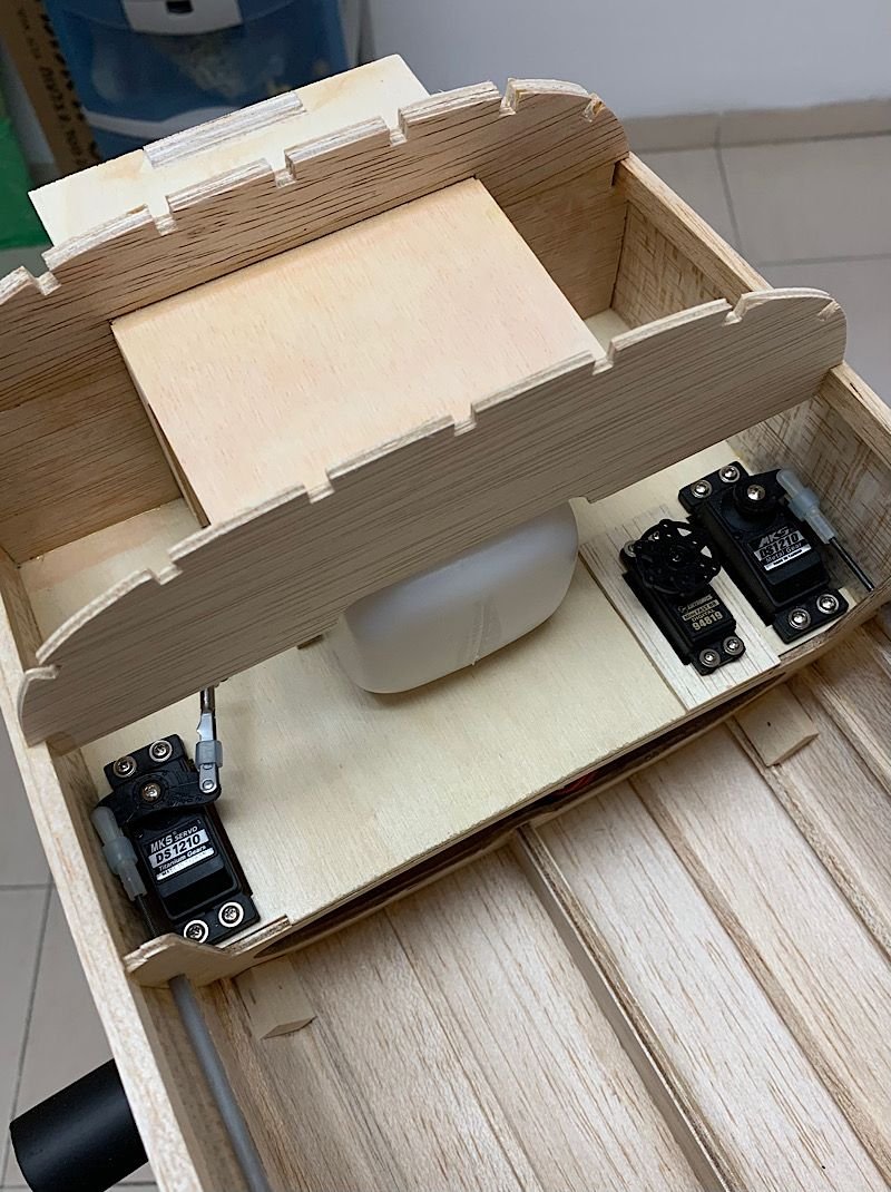
Although the plan shows a 12oz tank, I got this 14oz tank aligned in the conventional orientation without protruding back beyond the instrument panel.
Still ample room for the engine and mount.
Gives me peace of mind regarding fuel delivery to the engine...


