


LED Light Help
 10-13-2018, 06:49 AM
#1

Purchased this drop down landing light a while back, but need some help:
What is the purple covered electronics board attached to it ?
Also came with the Y cable pictured-not sure what the intent of that was ?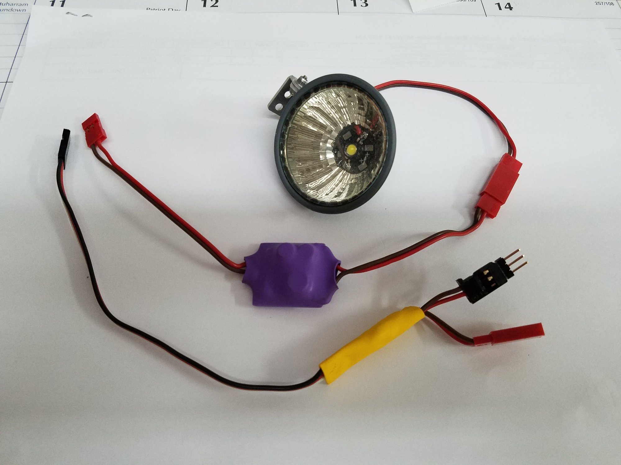
I am not that familiar with lighting-thanks in advance for helping me.
Mike O.
What is the purple covered electronics board attached to it ?
Also came with the Y cable pictured-not sure what the intent of that was ?
I am not that familiar with lighting-thanks in advance for helping me.
Mike O.
Last edited by IFLYBVM2; 10-13-2018 at 06:50 AM. Reason: text

 10-13-2018, 12:31 PM
#5

My Feedback: (3)
The �yellow� cable assembly appears to be a switch assembly. The connector on the left side (input) appears to be 3 wires while the right side (output) is only 2 wires which is switched Rx voltage
The �purple�cable assembly appears to be a voltage regulator, based on what looks tore under the heat shrink. If I were to guess, it is a step down regulator, so you don�t apply too much voltage to the LEDs.
The 2 pin output from thev�yellow� will connect to the 2 pin input cable on the �purple�
A simple setup would be to connect a battery (again start with 4.8 or 6 to start) directly to the 2 pin �purple� input connector and verify the LED lights.
To test it with the switch. you will need a battery and a receiver or servo simulator/tester.
Note: depending on your available voltage at the Rx, you may or mat not need the outdoor voltage module...but it�s safe to start with it to help,protect the LEDs against overvoltage/overcurrent.
Hope this helps ...
10-13-2018, 12:39 PM
#6
The �yellow� cable assembly appears to be a switch assembly. The connector on the left side (input) appears to be 3 wires while the right side (output) is only 2 wires which is switched Rx voltage
The �purple�cable assembly appears to be a voltage regulator, based on what looks tore under the heat shrink. If I were to guess, it is a step down regulator, so you don�t apply too much voltage to the LEDs.
The 2 pin output from thev�yellow� will connect to the 2 pin input cable on the �purple�
A simple setup would be to connect a battery (again start with 4.8 or 6 to start) directly to the 2 pin �purple� input connector and verify the LED lights.
To test it with the switch. you will need a battery and a receiver or servo simulator/tester.
Note: depending on your available voltage at the Rx, you may or mat not need the outdoor voltage module...but it�s safe to start with it to help,protect the LEDs against overvoltage/overcurrent.
Hope this helps ...
The �purple�cable assembly appears to be a voltage regulator, based on what looks tore under the heat shrink. If I were to guess, it is a step down regulator, so you don�t apply too much voltage to the LEDs.
The 2 pin output from thev�yellow� will connect to the 2 pin input cable on the �purple�
A simple setup would be to connect a battery (again start with 4.8 or 6 to start) directly to the 2 pin �purple� input connector and verify the LED lights.
To test it with the switch. you will need a battery and a receiver or servo simulator/tester.
Note: depending on your available voltage at the Rx, you may or mat not need the outdoor voltage module...but it�s safe to start with it to help,protect the LEDs against overvoltage/overcurrent.
Hope this helps ...


 10-11-2021, 03:28 AM
#10

Thank you, ltc, for describing what each wire does, I have been looking for a solution to this problem for a very long time, and thanks to you, I finally realized where I had a mistake. By the way, I also encountered a similar problem when I ordered LED Tape from this site ukled.co.uk. Unfortunately, when they asked me if I needed to explain how to install everything, I said I knew everything and didn't need an explanation. How stupid I was! Thank you again, ltc, very much; otherwise, I would have had to surf the Internet for a long time. Maybe I wouldn't have found what I was looking for.


