


Nick’s TopRC L-39 build thread
 09-03-2022, 09:57 AM
#26
Senior Member
My Feedback: (2)
Join Date: Aug 2002
Location: Longview TX
Posts: 157
Likes: 0
Received 0 Likes
on
0 Posts
I guess if I have any complaints about the plane is that whoever painted the numbers needs to take a little time to make sure it is straight especially for the price.
Eddie
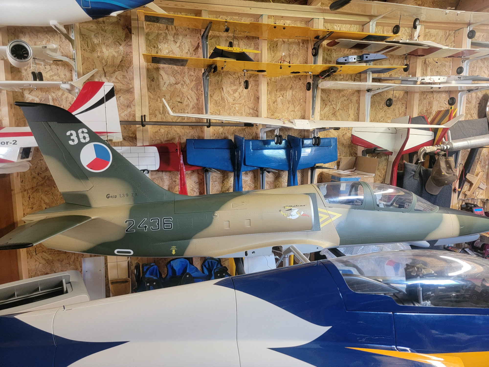
The other side is ok.
Eddie
The other side is ok.
 09-05-2022, 04:53 PM
#27

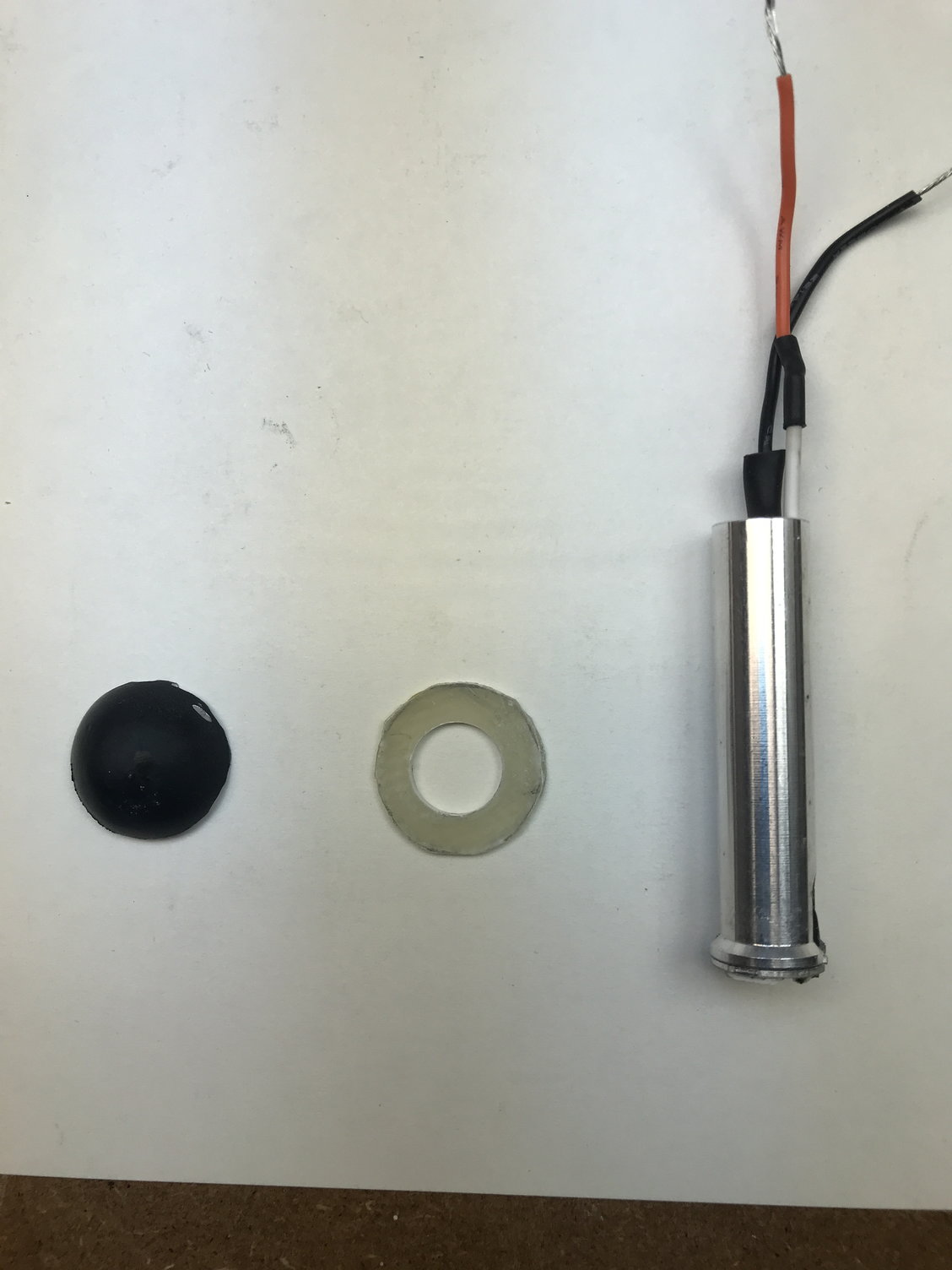
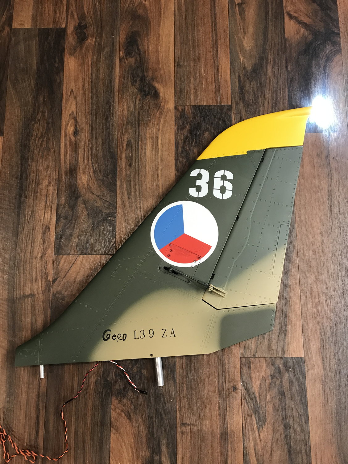
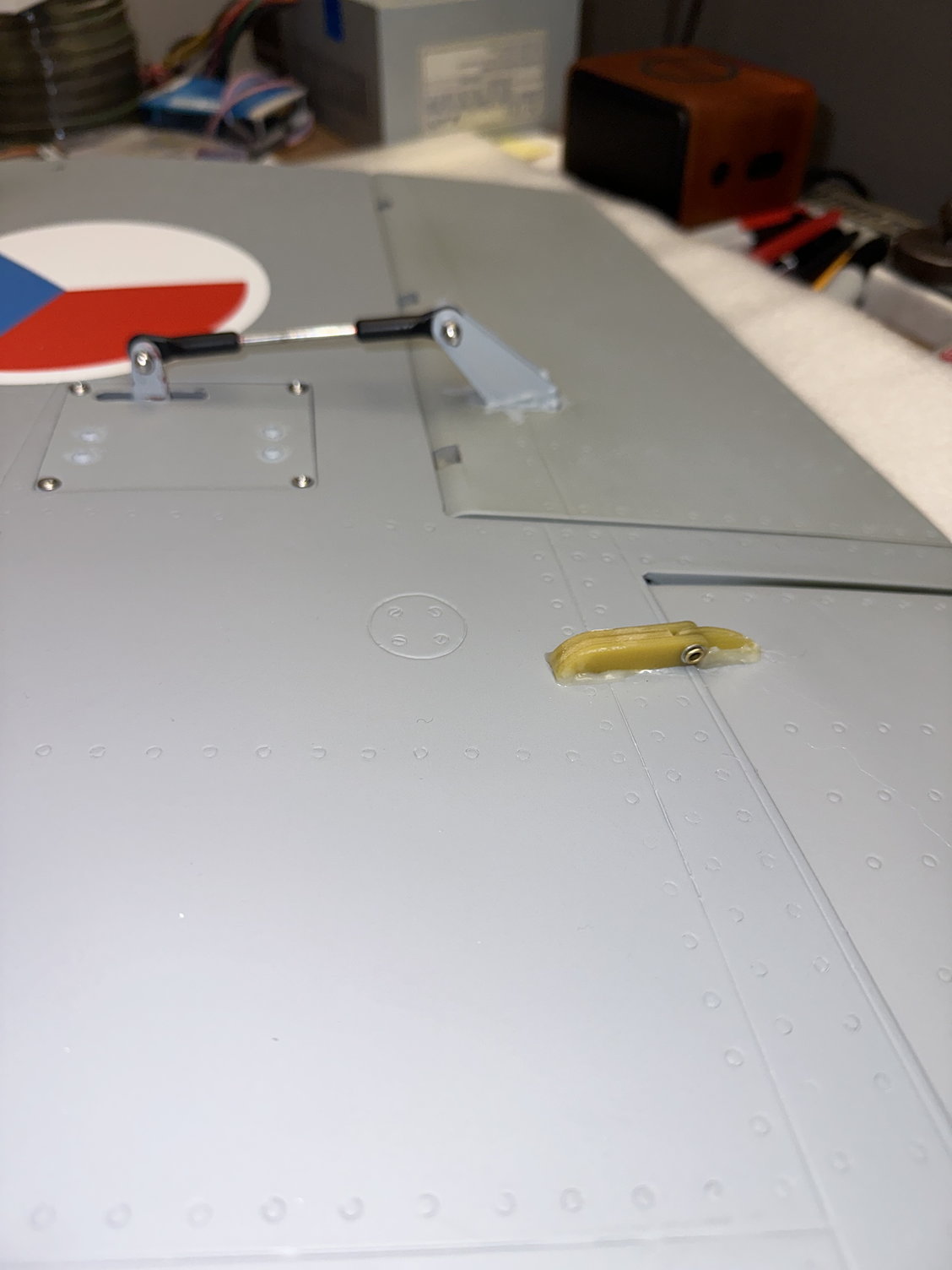
I mentioned I was going to add a rear facing, white strobe to the top of the fin. I removed a portion of the rounded, top rear fin and added a fiberglass circular vertical bulkhead to house the strobe. BTW My rudder control rod length from the center to the center of the ball links is approximately 3.25"; this can vary depending on your servo arm length. Don't forget to epoxy the aluminum fin locating tube into the bottom of the fin. You will see that I painted the servo screws and the various control arms from sample paints I had mixed at a big box store.
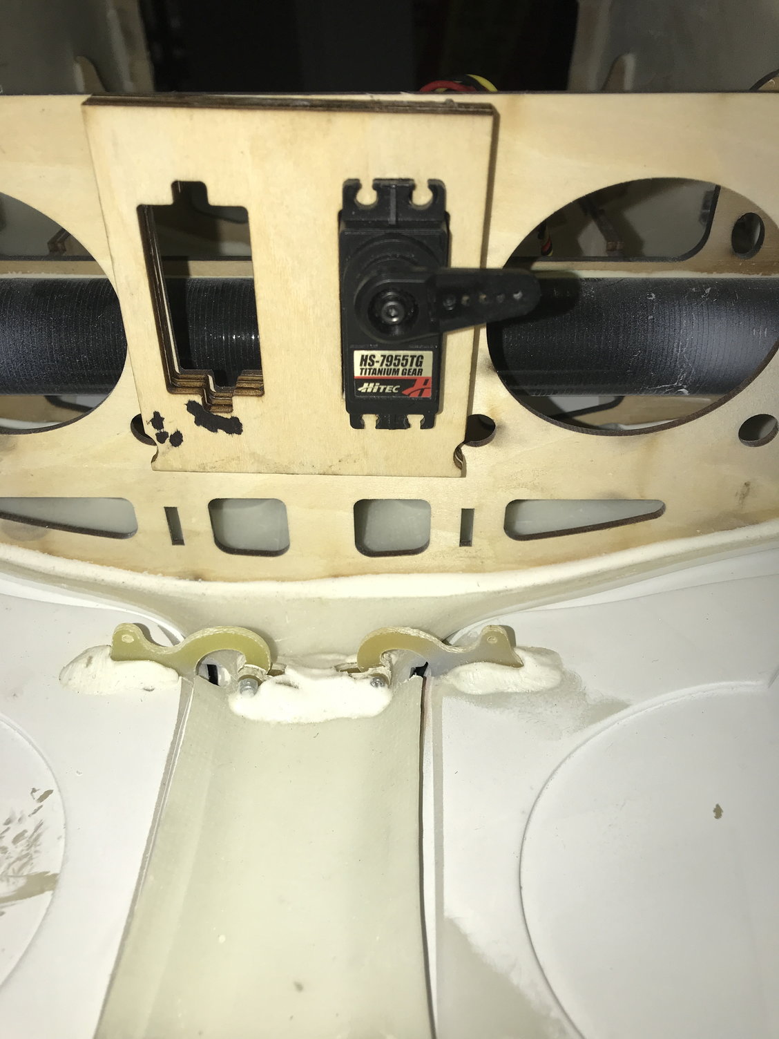
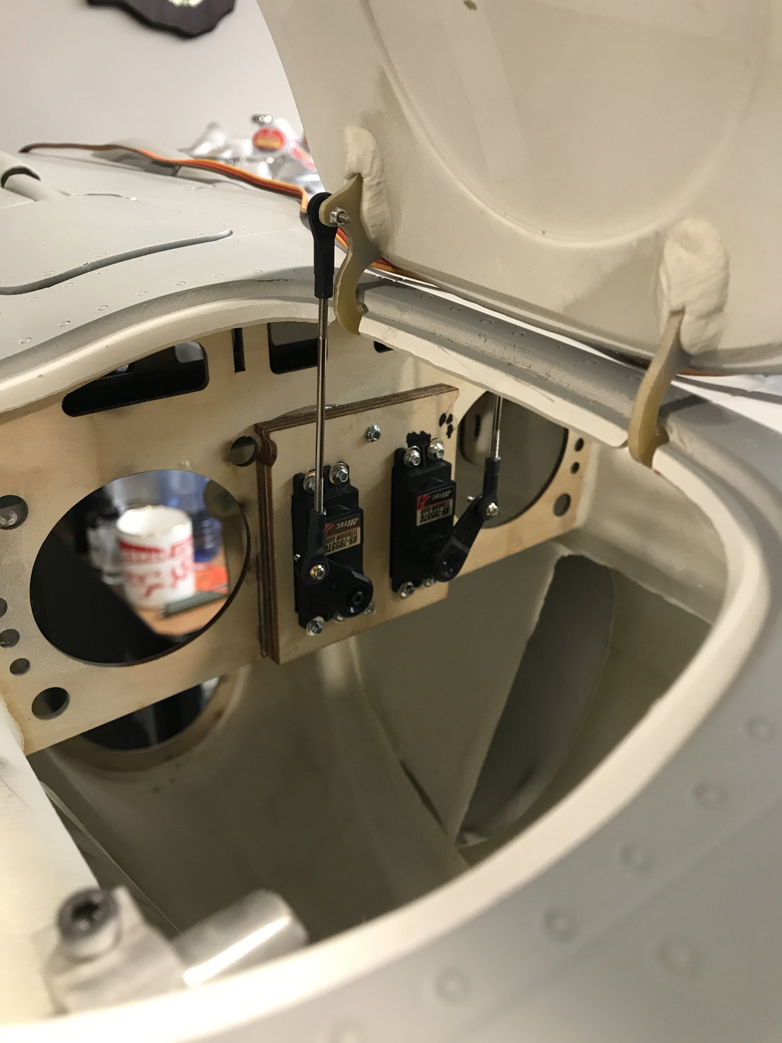
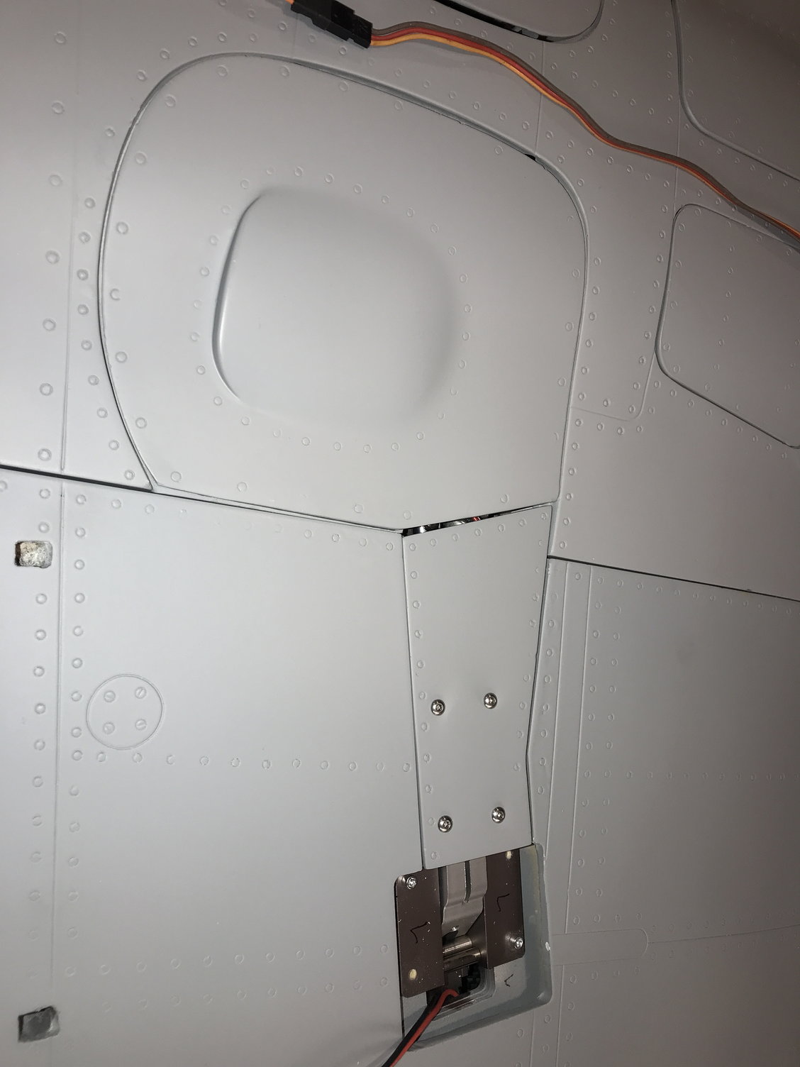
I also, with some help, determined the usage of the laser cut dual servo plywood mount in the misc parts bag. It is used to bring the main gear door servos out away from the bulkhead to line up with the gear door hinges (see Pic).
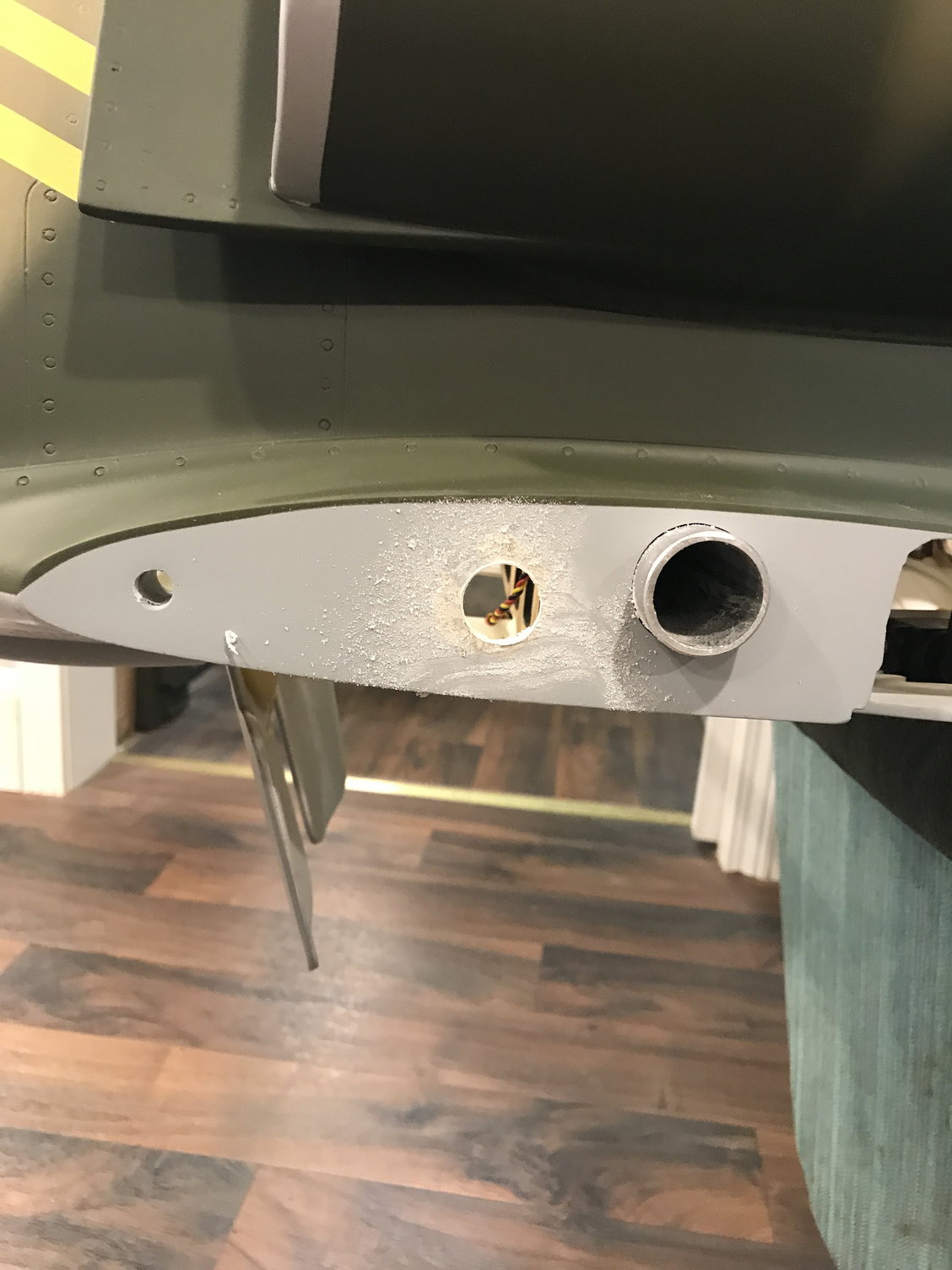
A few of us have come to the consensus that servo, gear, and brake wires from each wing should exit through the existing hole in from of the wing tube. You will then need to make a mating hole in the fuse on each side. The hole center is approximately 4.375" back from the leading edge and .875" up from the bottom of the wing (see Pic).
More later.....
I also, with some help, determined the usage of the laser cut dual servo plywood mount in the misc parts bag. It is used to bring the main gear door servos out away from the bulkhead to line up with the gear door hinges (see Pic).
A few of us have come to the consensus that servo, gear, and brake wires from each wing should exit through the existing hole in from of the wing tube. You will then need to make a mating hole in the fuse on each side. The hole center is approximately 4.375" back from the leading edge and .875" up from the bottom of the wing (see Pic).
More later.....
10-11-2022, 04:39 AM
#28
OK Back in Ohio and back to work on the L-39. I decided to work on the main gear doors.
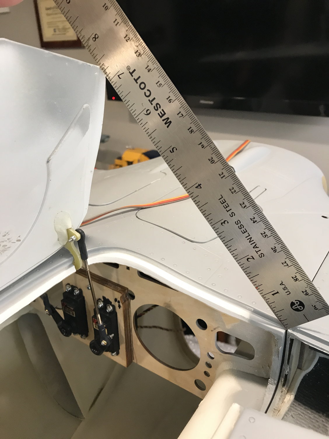
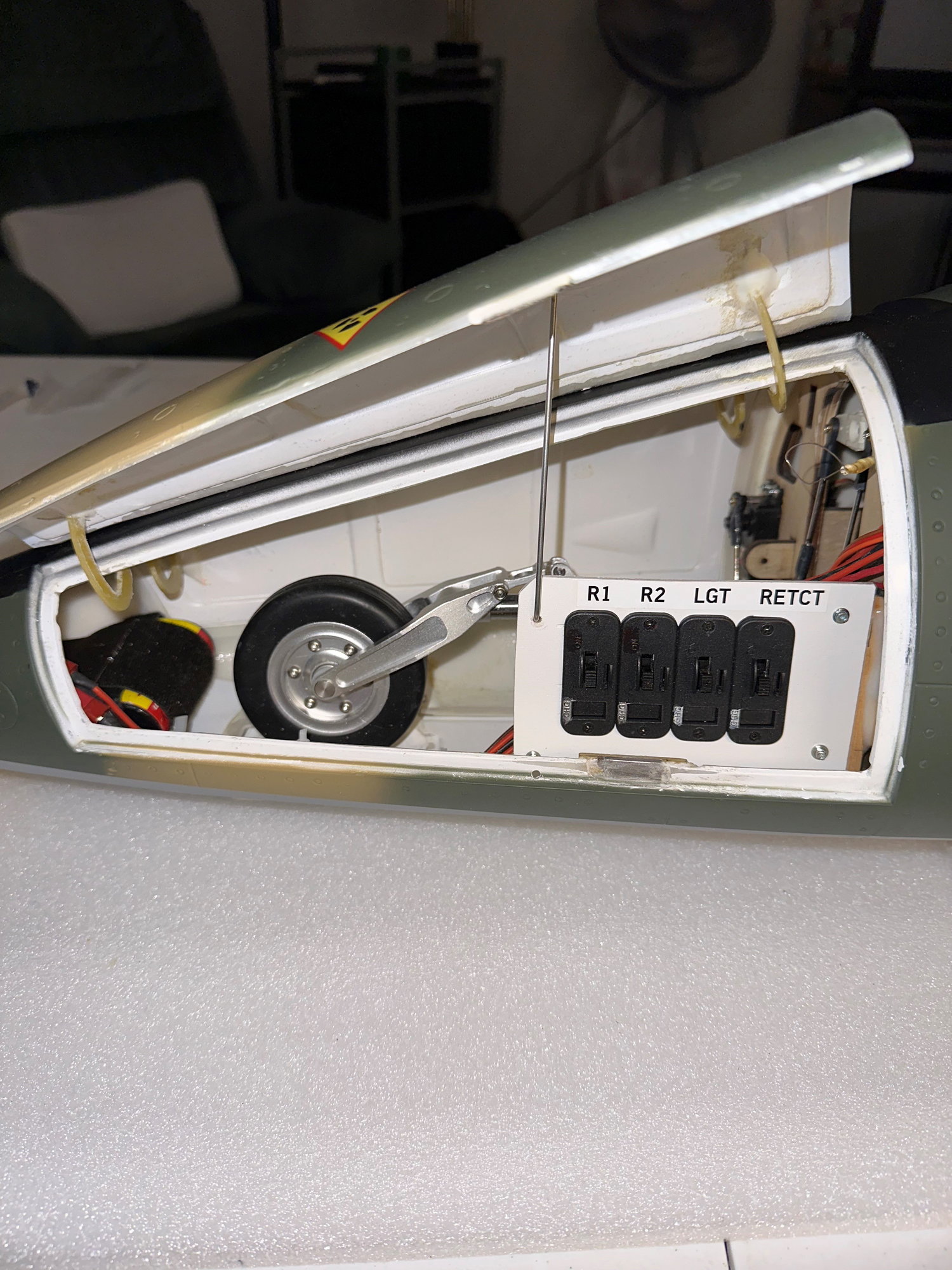
I utilized the small ball links, small dia rod and a 1 " servo arm to get the door to open 7.25" from the leading edge of the door to the fuse edge (see pic). This distance allows the wheel to clear the door as it retracts into the fuse. The TopRC brake and retract controller makes it easy to adjust servo / door travel. I only connected one end of the ball link rod, the servo arm end, while adjusting the travel as to not overdrive the doors. Once I had the travel close I connected the other rod end to the door hinge.
Again, the supplied hardware is totally usable - very refreshing!
I temporarily mounted the retracts. The supplied screws are wood screws with a Phillips head that I won't be using. I may use socket head wood screws or blind nuts with socket head machine screws; haven't made a final decision yet. I have used both types with success over the years.
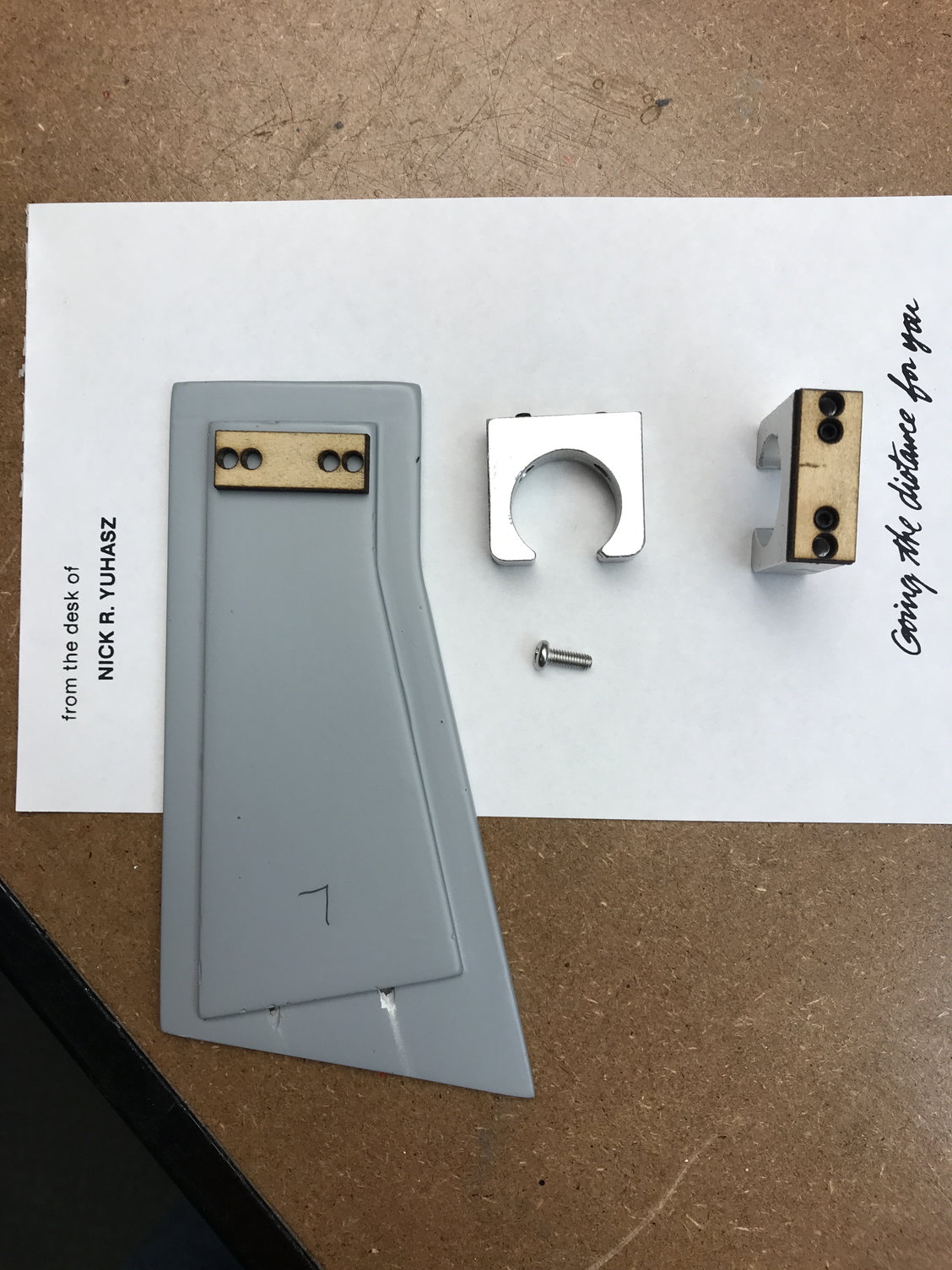
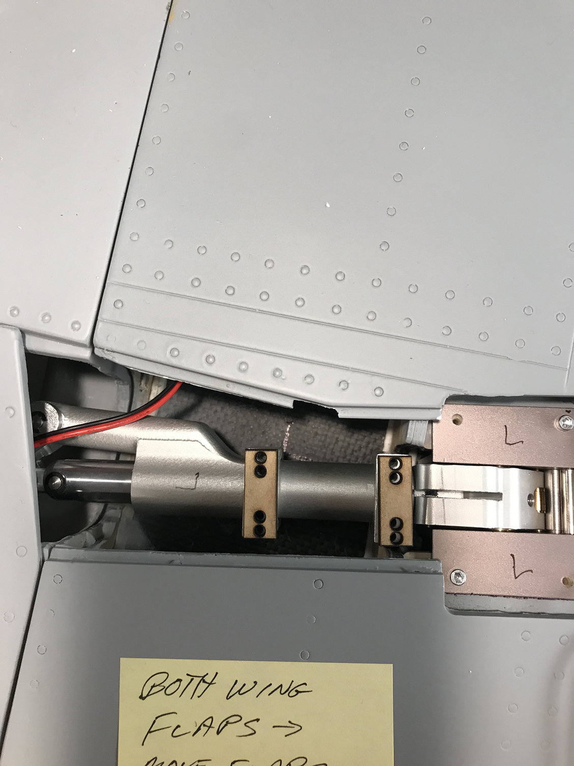
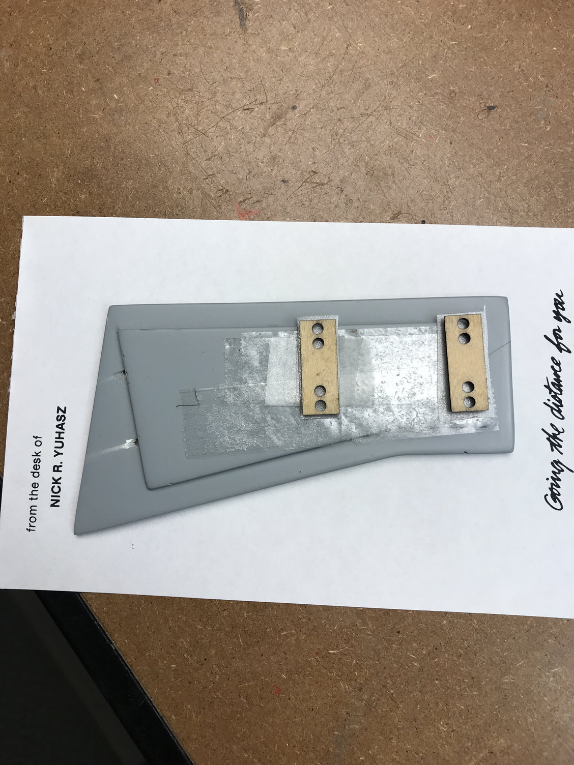
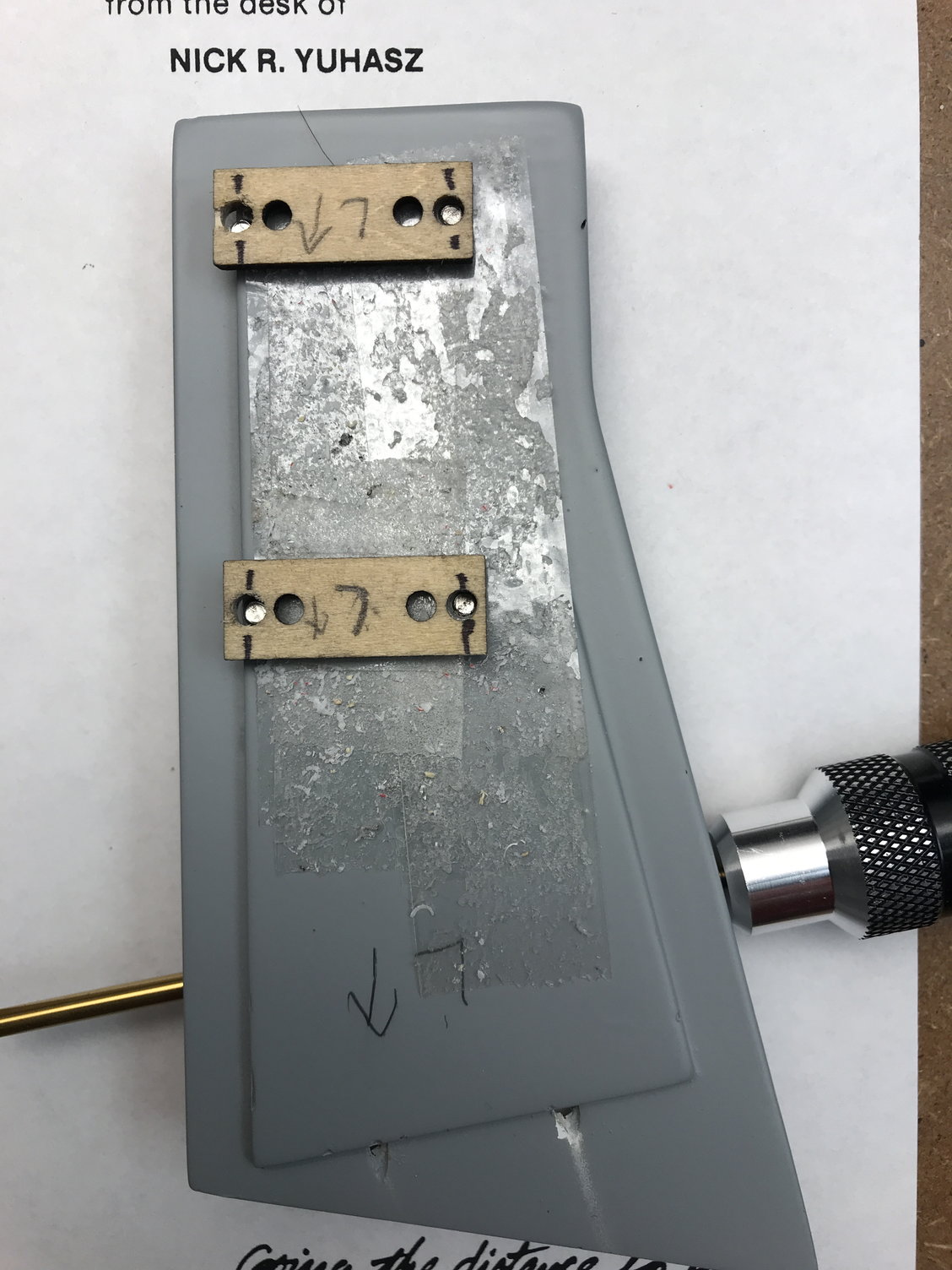
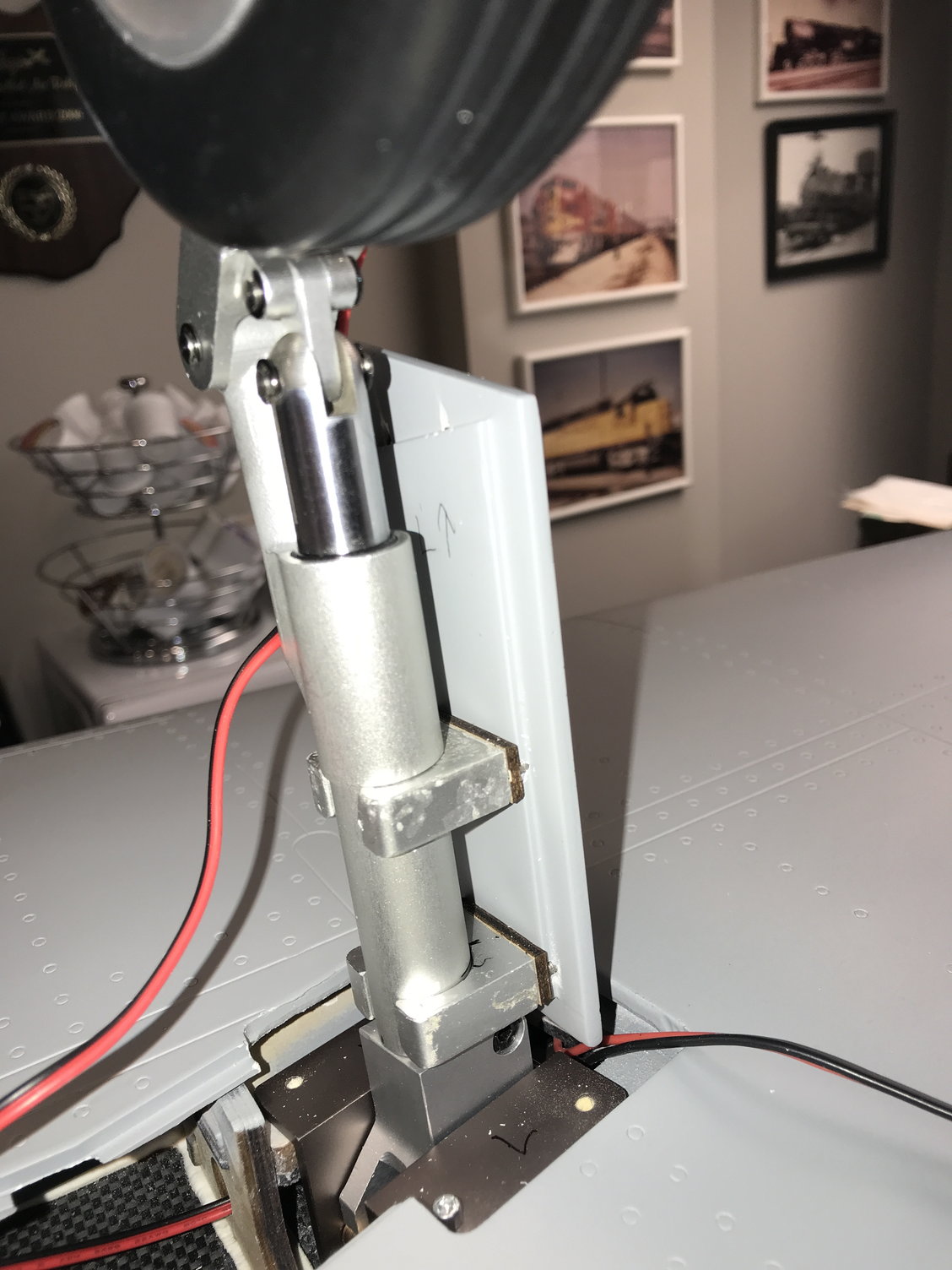
Once the gear retracts have been positioned properly so the strut and wheel clear all obstacles, you can mount the strut cover to the strut. We are supplied with everything to easily mount the covers - aluminum clamps, laser drilled wood mounting plywood, and the covers (see pic). I proceeded to add the aluminum clamps to the strut, place in retracts and strut in the retracted position then add double sided tape to the clamps and temporarily add the ply mounts to clamps (see pic). Also add double sided tape to the inside of the strut cover. Now carefully place the strut cover in position over the clamps and press down ensuring clearance around the cover and between the wing and fuse. When you lift the strut cover off the clamps, the plywood mounts should now be temporarily stuck to the inside of the strut cover (see pic). This will allow you to drill the mounting holes (outside two holes in each ply mount) from the inside of the cover for the 3mm dia 12mm long button head screws (see pics).
More later...
Nick
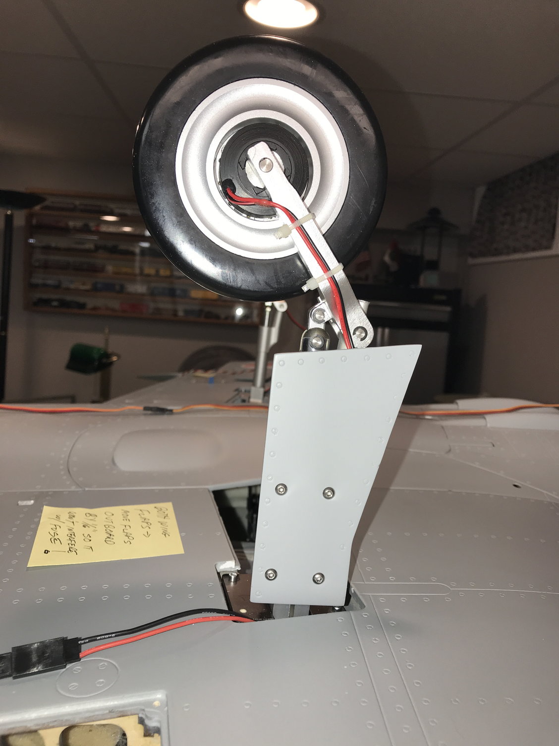
I utilized the small ball links, small dia rod and a 1 " servo arm to get the door to open 7.25" from the leading edge of the door to the fuse edge (see pic). This distance allows the wheel to clear the door as it retracts into the fuse. The TopRC brake and retract controller makes it easy to adjust servo / door travel. I only connected one end of the ball link rod, the servo arm end, while adjusting the travel as to not overdrive the doors. Once I had the travel close I connected the other rod end to the door hinge.
Again, the supplied hardware is totally usable - very refreshing!
I temporarily mounted the retracts. The supplied screws are wood screws with a Phillips head that I won't be using. I may use socket head wood screws or blind nuts with socket head machine screws; haven't made a final decision yet. I have used both types with success over the years.
Once the gear retracts have been positioned properly so the strut and wheel clear all obstacles, you can mount the strut cover to the strut. We are supplied with everything to easily mount the covers - aluminum clamps, laser drilled wood mounting plywood, and the covers (see pic). I proceeded to add the aluminum clamps to the strut, place in retracts and strut in the retracted position then add double sided tape to the clamps and temporarily add the ply mounts to clamps (see pic). Also add double sided tape to the inside of the strut cover. Now carefully place the strut cover in position over the clamps and press down ensuring clearance around the cover and between the wing and fuse. When you lift the strut cover off the clamps, the plywood mounts should now be temporarily stuck to the inside of the strut cover (see pic). This will allow you to drill the mounting holes (outside two holes in each ply mount) from the inside of the cover for the 3mm dia 12mm long button head screws (see pics).
More later...
Nick
The following users liked this post:
bandit_av (10-11-2022)
10-16-2022, 06:25 AM
#30
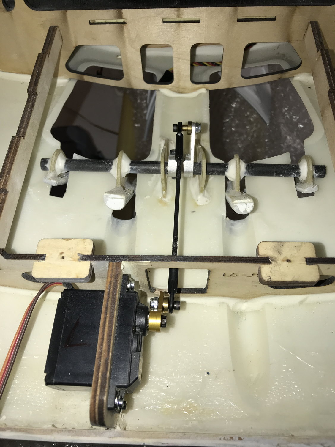
A relatively easy task is to install the Speed Brake servo. I decided to utilize an older JR 8611 servo. The supplied control rod and ball links would probably be sturdy enough, but I decided to utilize some 4-40 ball links and corresponding control rod I had laying around. I used a .75" servo arm and the control rod length including the ball links was 4.25" long. You may need to fine tune (sand) the speed brakes or the openings to get them to open or close smoothly. This is because the carbon fiber support rod that stretches across the speed brakes is just supported by simple holes in two fiberglass mounting surfaces and there is a little "play" in the support; ie. there are no true bearings to support the rod.
More later ....
More later ....
The following users liked this post:
bandit_av (10-17-2022)
11-01-2022, 05:53 AM
#31
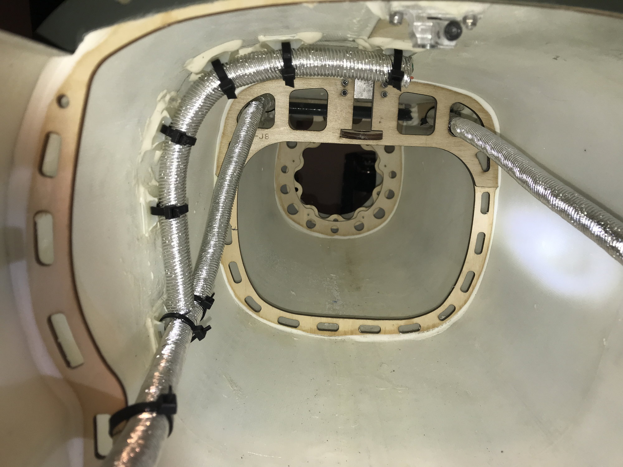
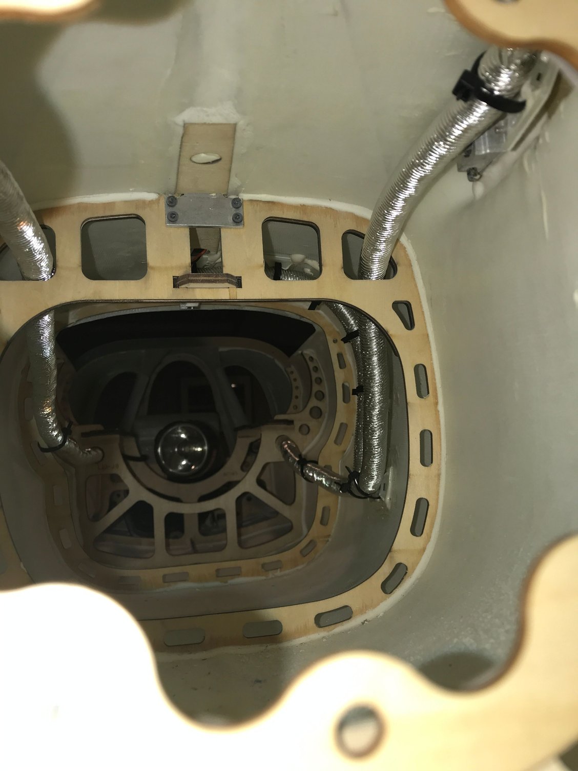
Decided I would run all the wiring to the rear of the jet. Rudder, both elevators, and fin lighting 20 ga wiring were encapsulated in heat-resistant Cool Tube Extreme until past the turbine mounts (see pics).
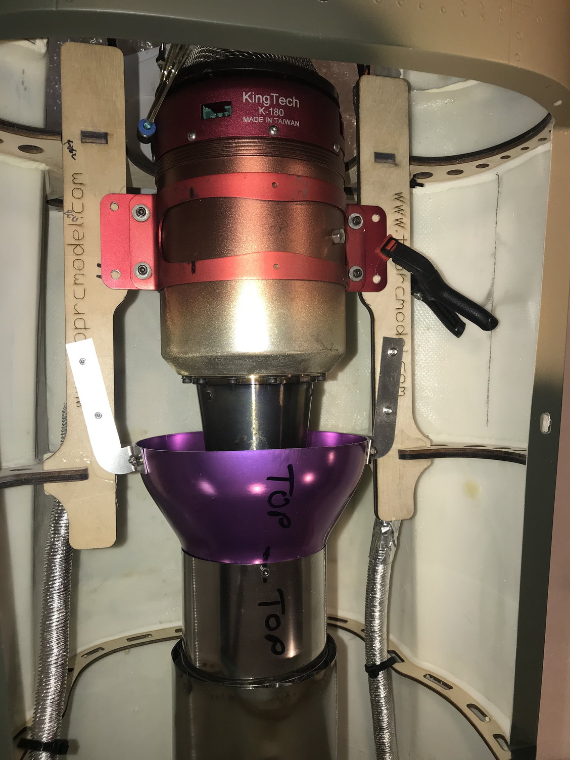
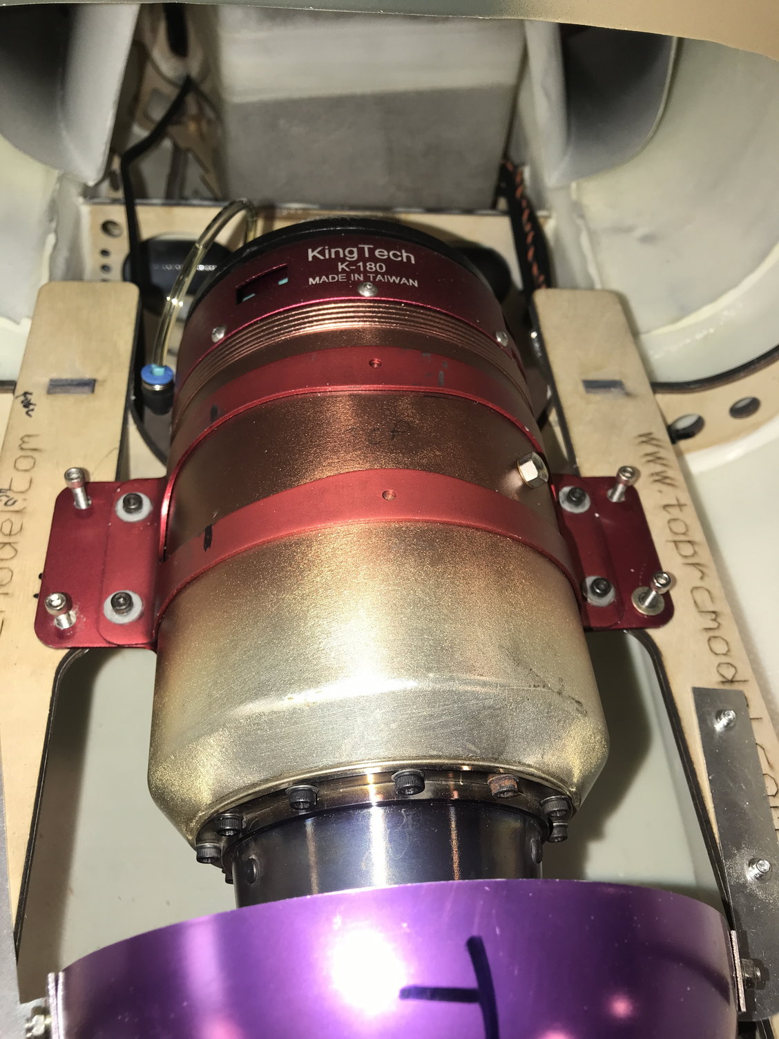
After mounting the bell mouth to the thrust pipe, I aligned the rear of the thrust pipe flush with the rear of the fuselage (it is cut at an angle to match the rear fuse). You must drill some mounting holes in the aluminum arms protruding from the bell mouth to mount them to the turbine mounting rails. At this point I positioned the K-180 nozzle 25mm from the end of the pipe (not the bell mouth as per the KingTech manual) and used 6-32 screws and blind nuts to mount the turbine (see pics).
More later....
View looking back towards tail.
Looking forward from tail.
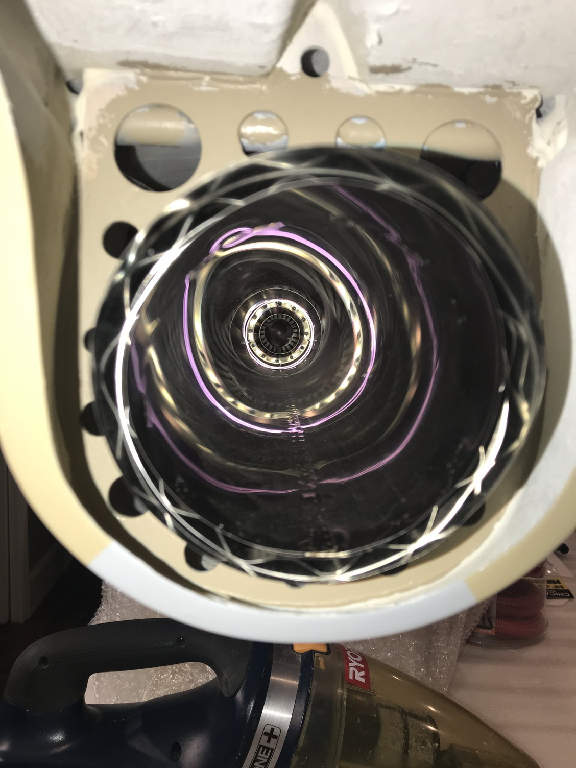
Pipe in place.
After mounting the bell mouth to the thrust pipe, I aligned the rear of the thrust pipe flush with the rear of the fuselage (it is cut at an angle to match the rear fuse). You must drill some mounting holes in the aluminum arms protruding from the bell mouth to mount them to the turbine mounting rails. At this point I positioned the K-180 nozzle 25mm from the end of the pipe (not the bell mouth as per the KingTech manual) and used 6-32 screws and blind nuts to mount the turbine (see pics).
More later....
View looking back towards tail.
Looking forward from tail.
Pipe in place.
11-01-2022, 05:19 PM
#32
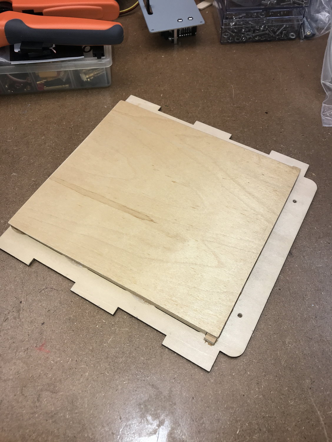
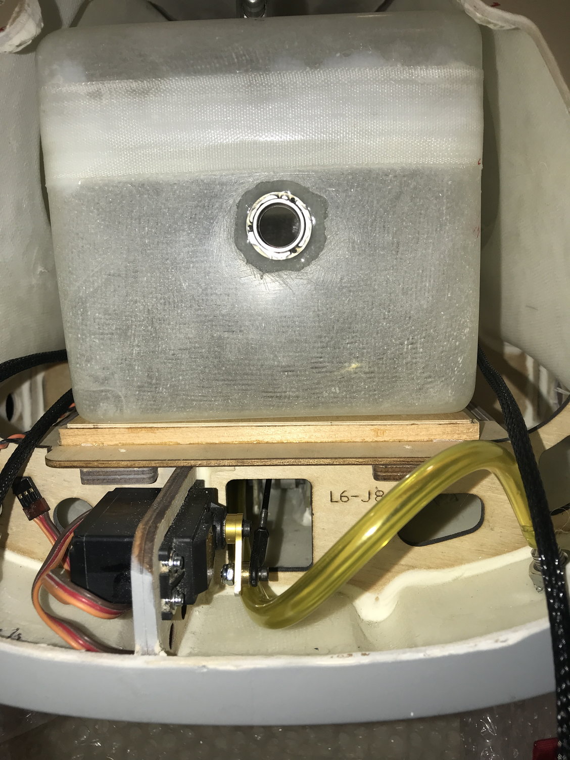
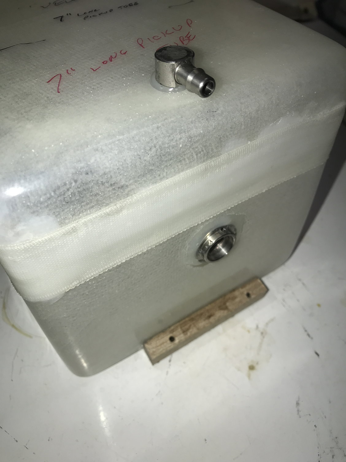
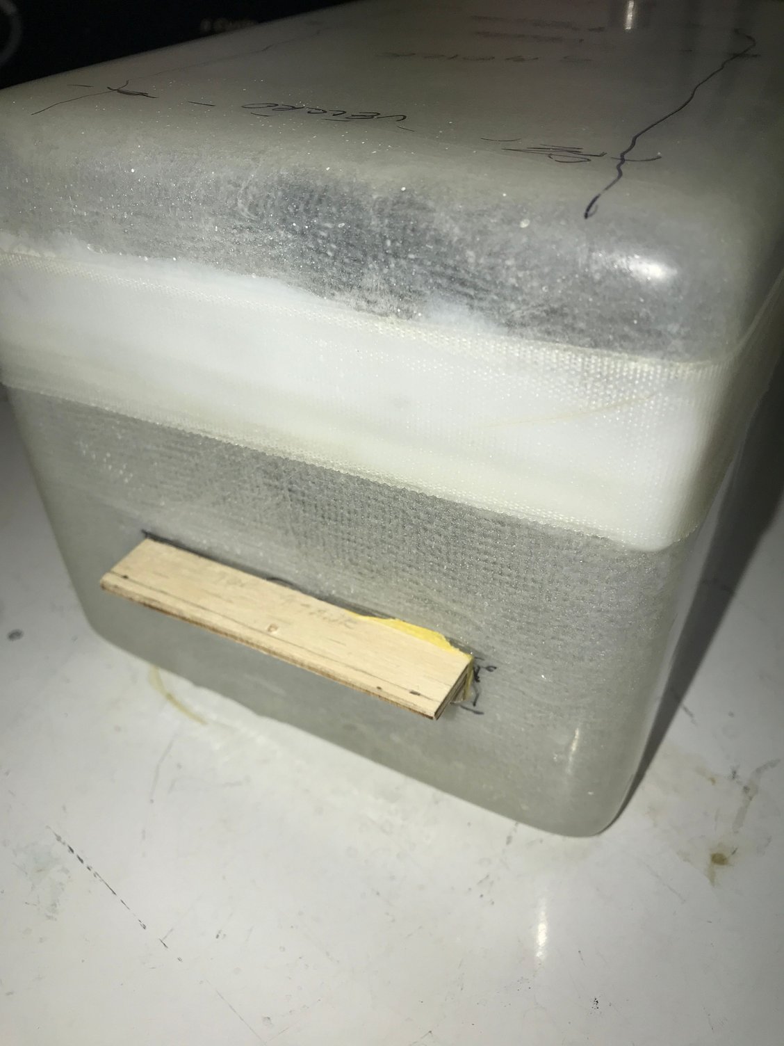
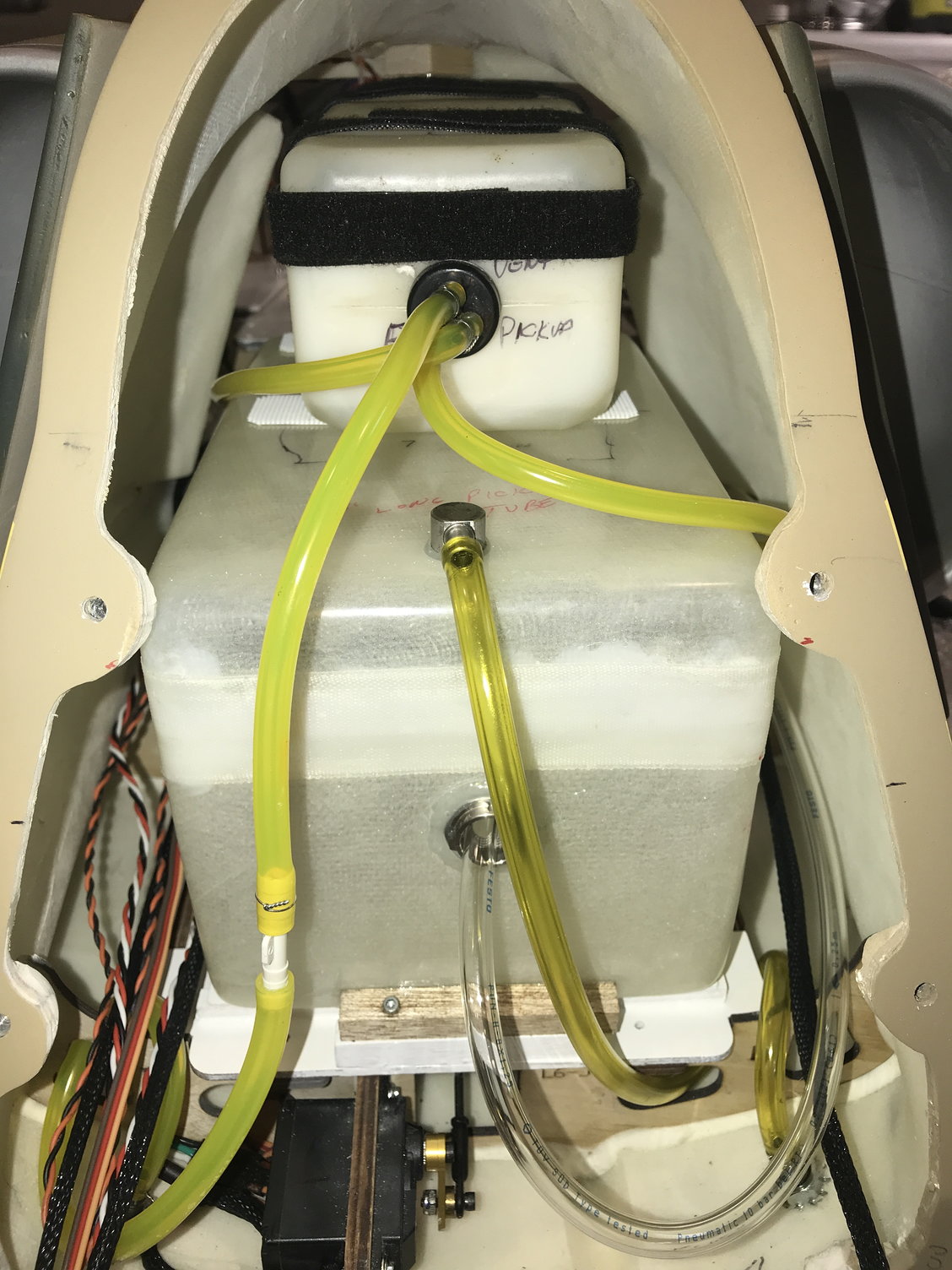
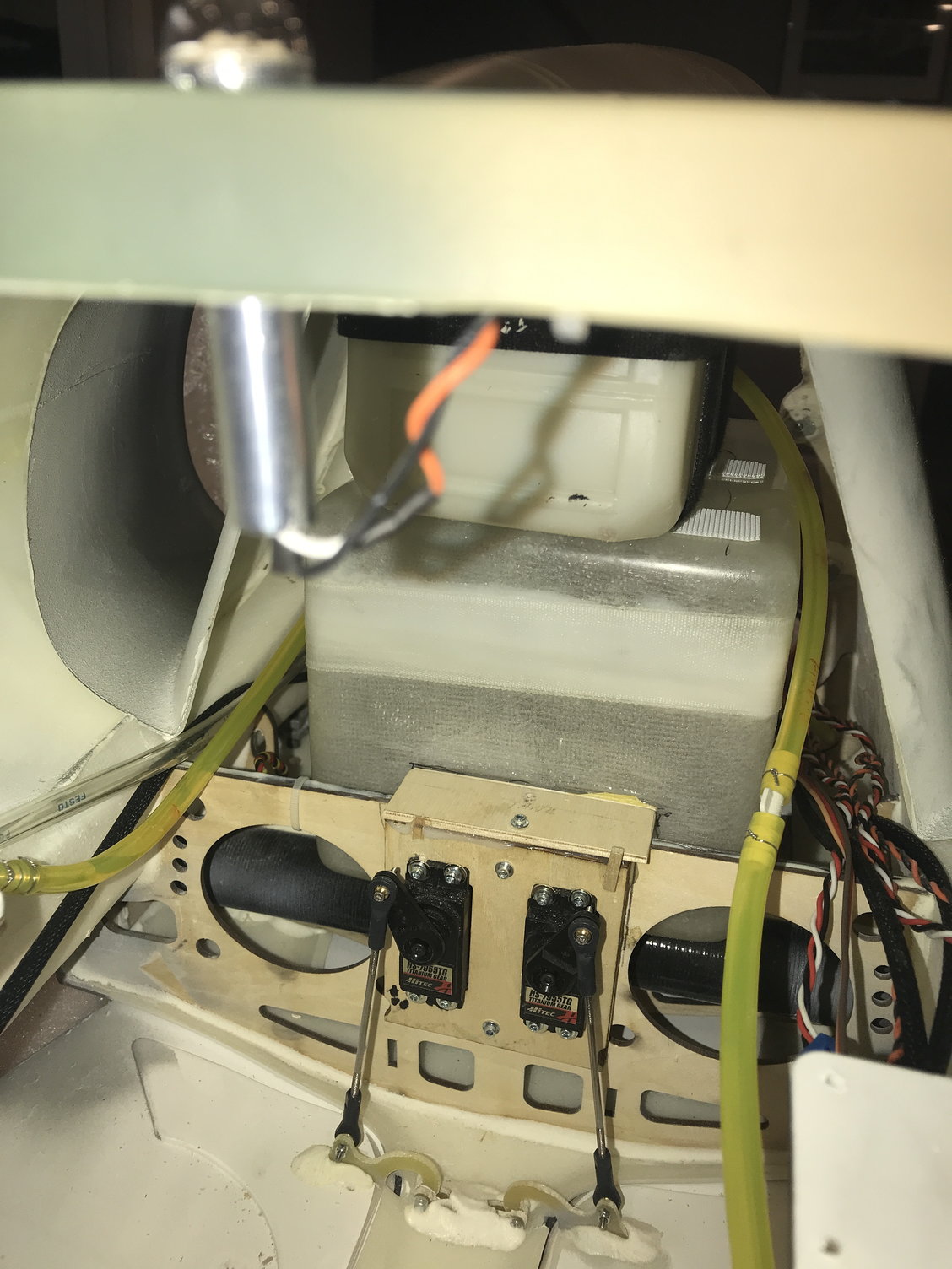
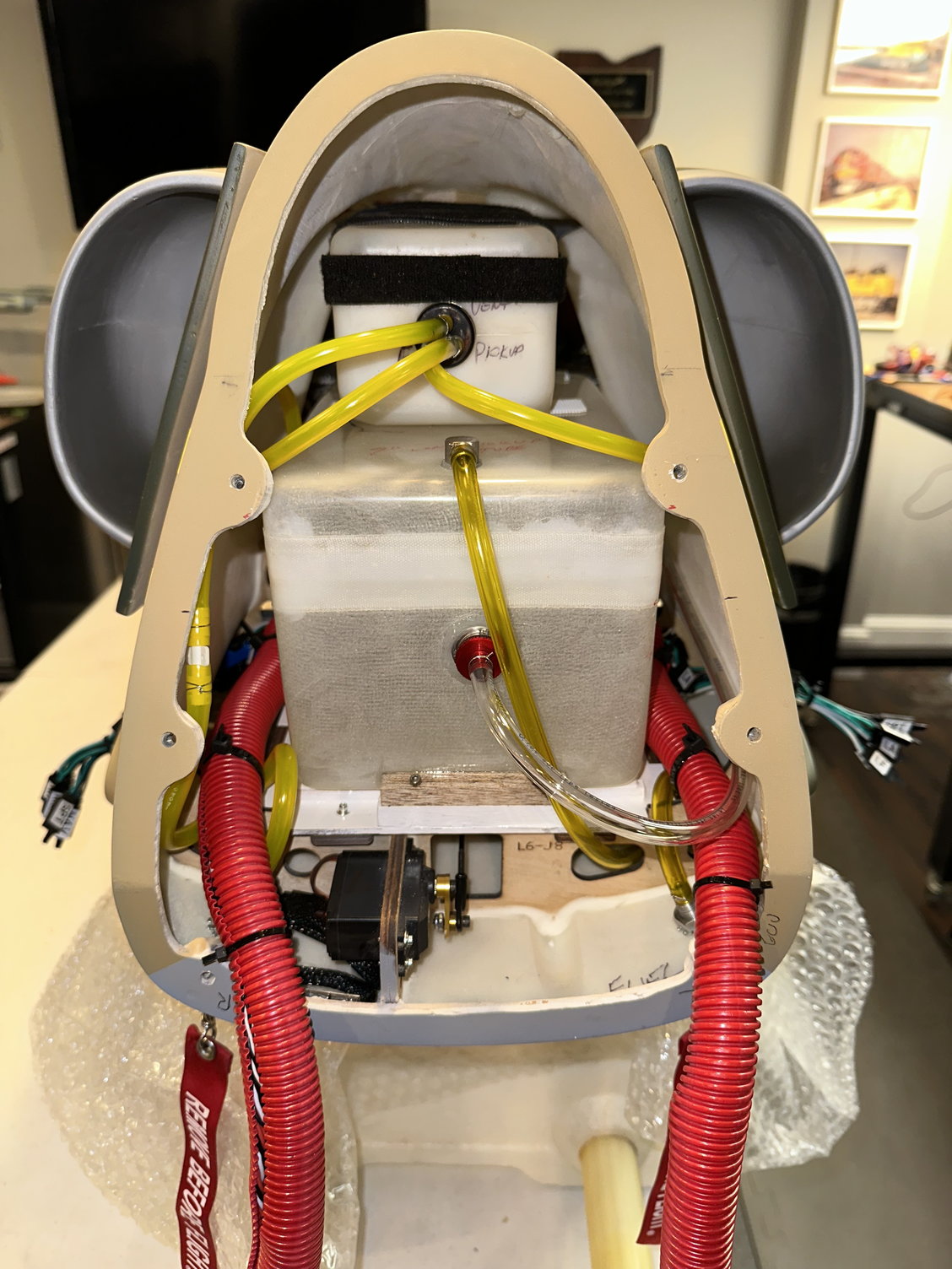
So first hurdle with the build: You will discover that with the main fuel tank in place on it's mounting platform and back against the wing tube, it will interfere with the rear cockpit going in place by about a .25 inches. That is, the tank extends too far into the front of the fuselage. My solution was to add a second platform .25" high on top of the original platform which will allow the tank to be moved rearward and essentially the rear of the fuel tank will sit on top of the wing tube. I also decided to mount the tank by adding ply and hardwood extensions Hysol-ed to it that can be screwed to the platform to hold the main tank in place. I placed my smoke tank on top of the main fuel tank held in place by Velcro.
More later.....
More later.....
11-05-2022, 02:58 PM
#33
Decided to mount all "wet" items (smoke and fuel tanks, pumps, and UAT) in the rear section of the fuselage. Greatly simplified the build and if I ever have to split the fuse for transport or shipping that configuration will make it vastly easier to do. I was able to complete the rear section of the fuselage today. In fact, I took the rear section outside today (77 degrees and very windy in Northern Ohio today - new record temperature for today), connected a receiver, and started the turbine and tested the smoke system - all OK and no leaks!
More later....
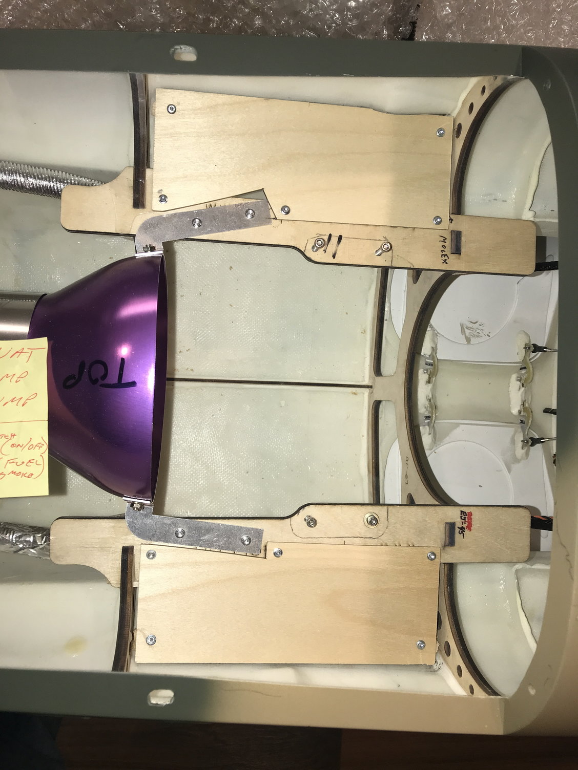
Created platforms for mounting ECU, switches, filling ports, etc
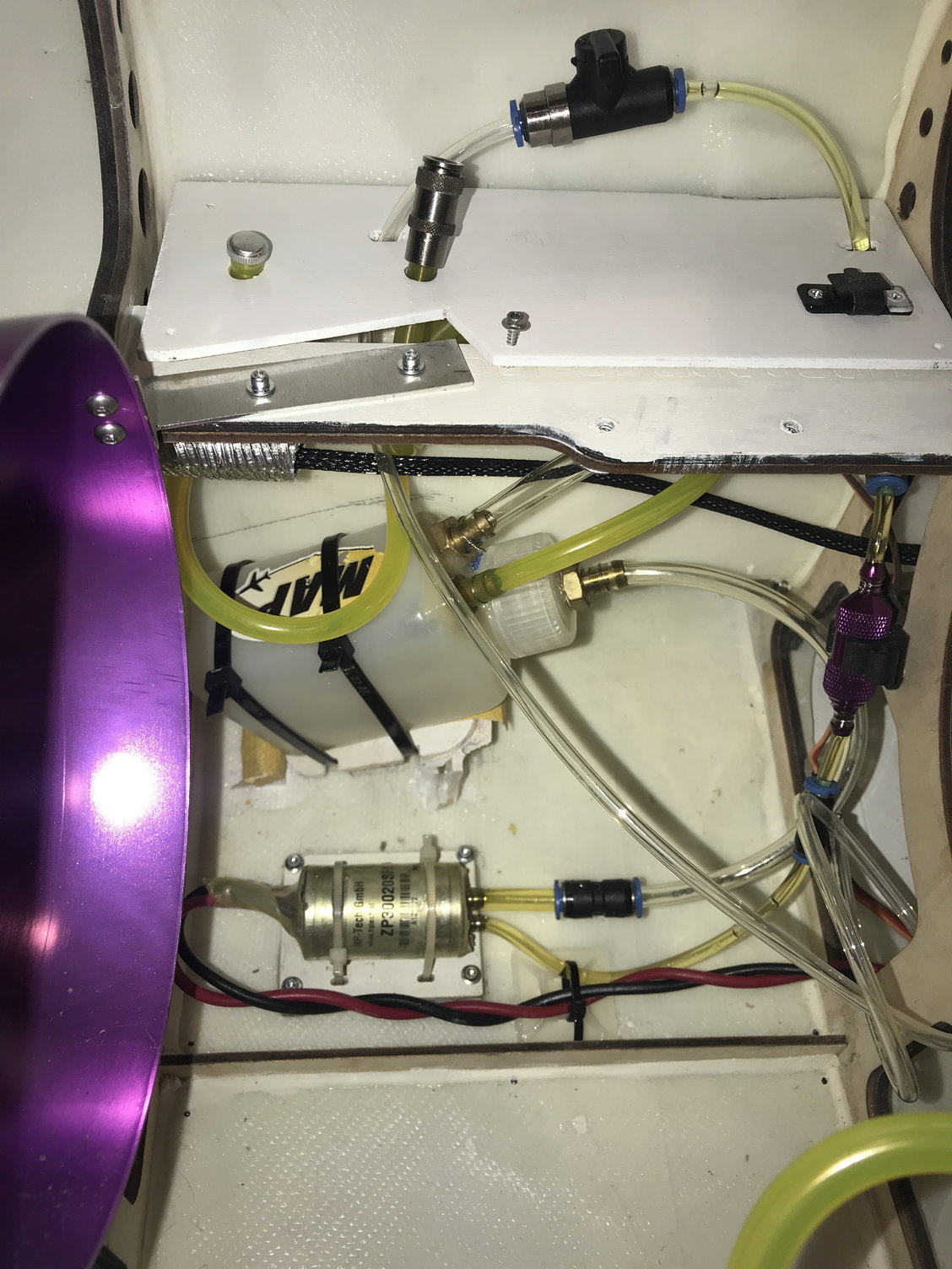
UAT and fuel pump
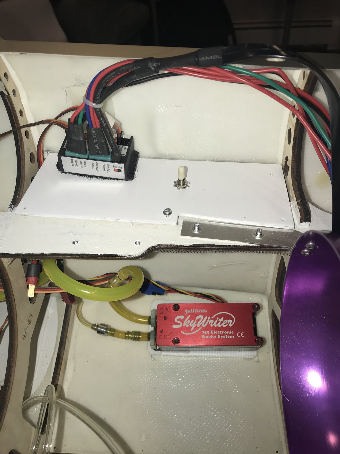
ECU and smoke pump
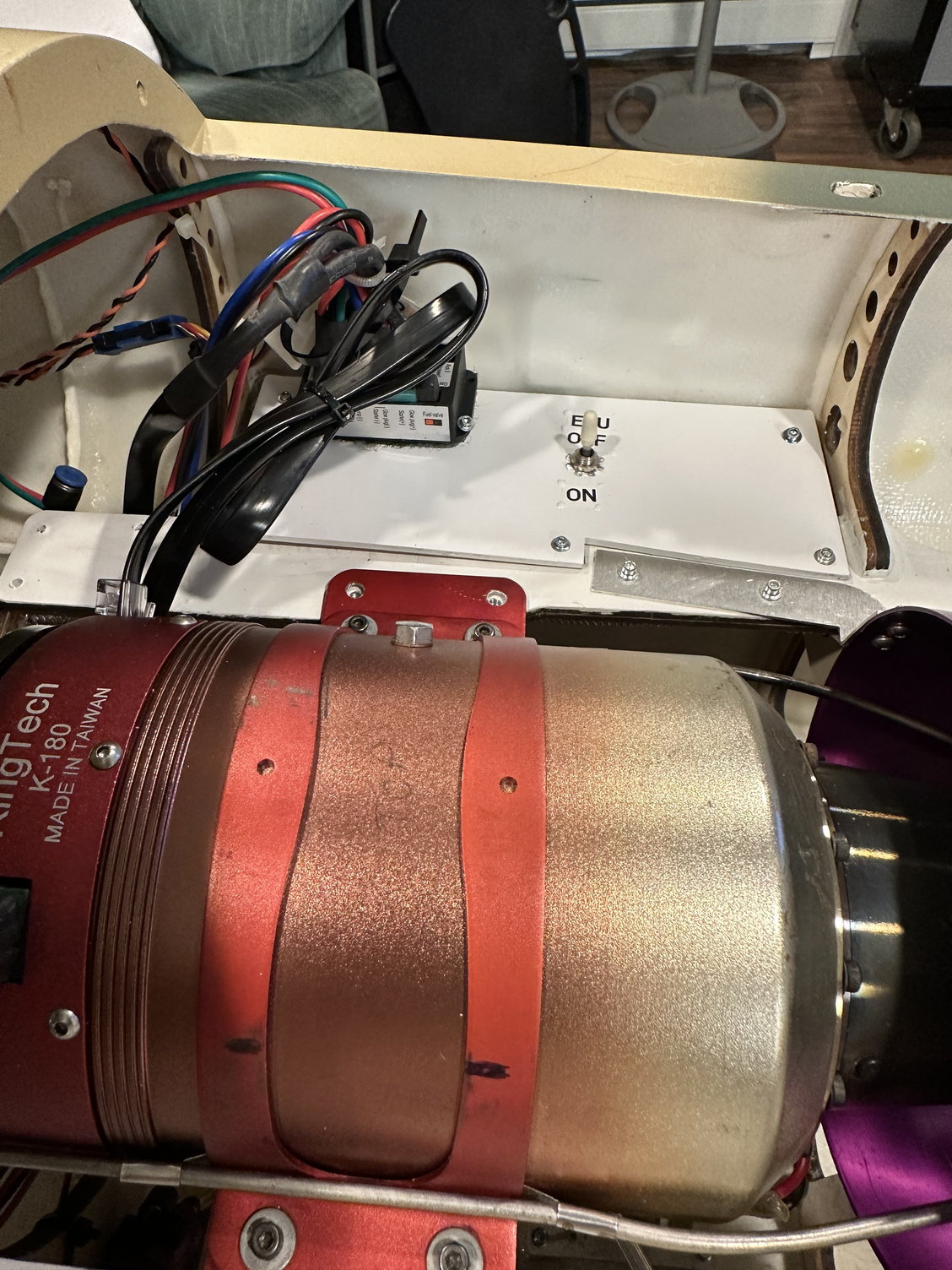
ECU
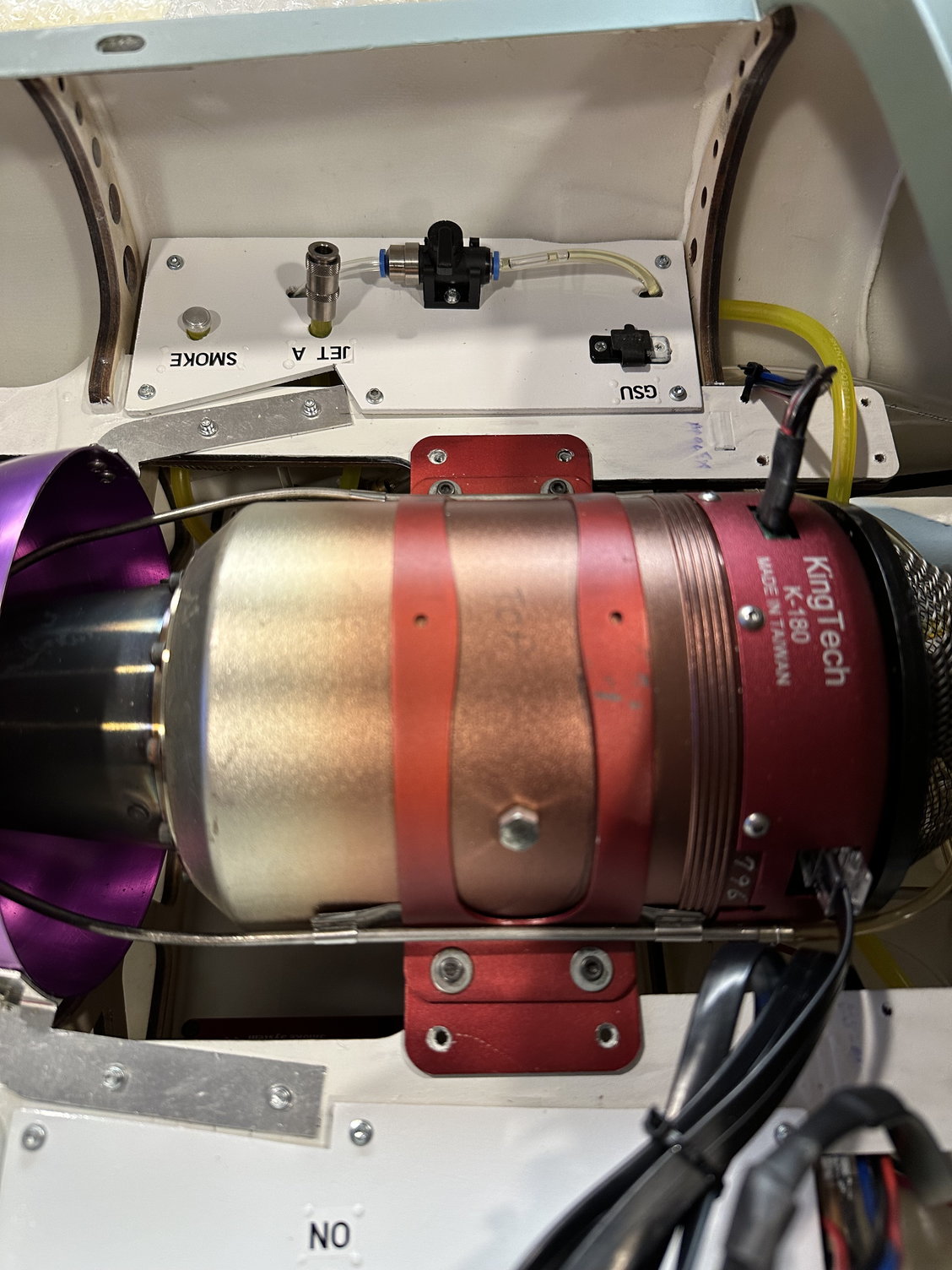
fuel valve and fill ports
Rear fuse complete with wire bundles leading forward.
More later....
Created platforms for mounting ECU, switches, filling ports, etc
UAT and fuel pump
ECU and smoke pump
ECU
fuel valve and fill ports
Rear fuse complete with wire bundles leading forward.
11-08-2022, 05:11 PM
#34
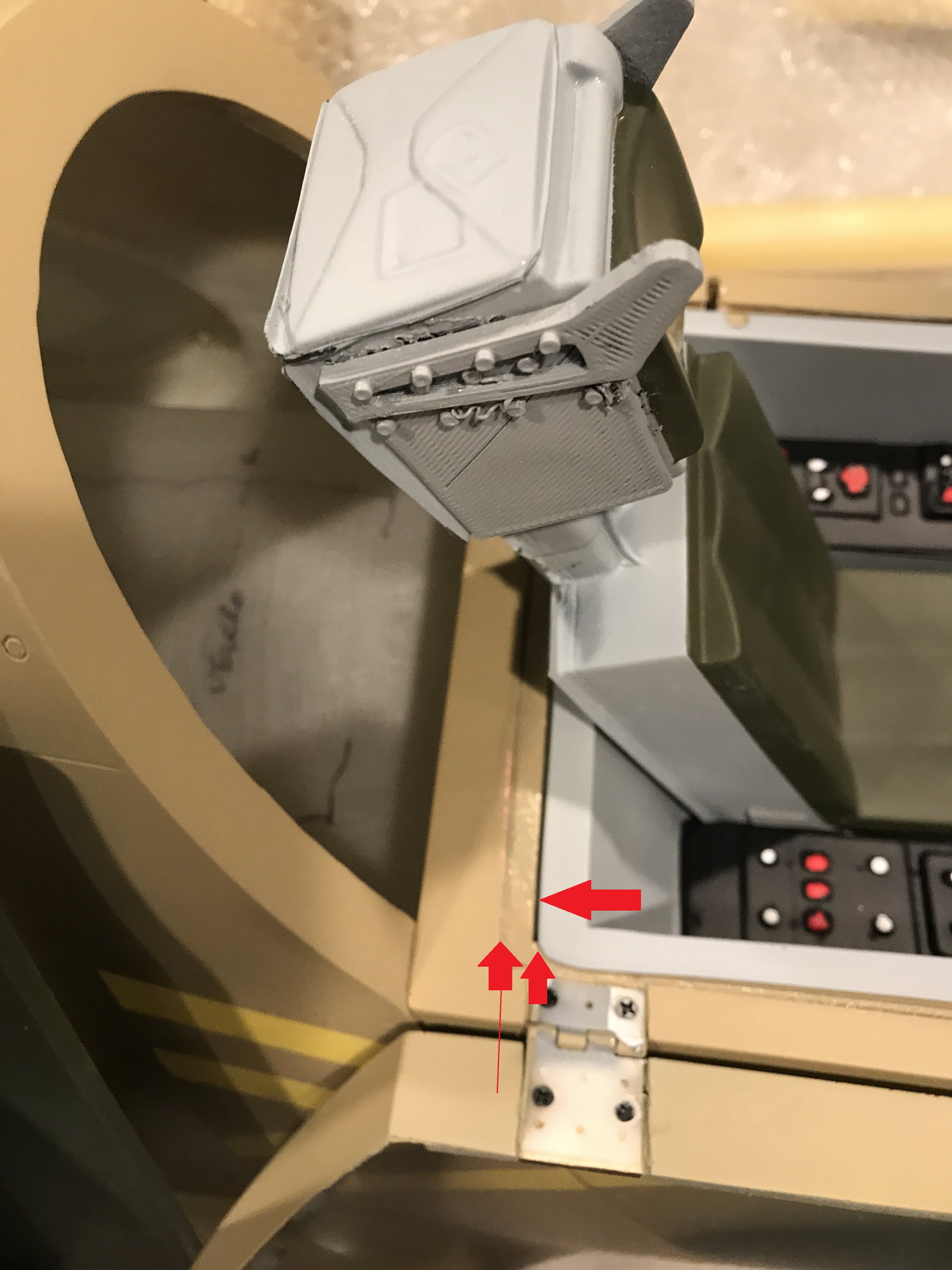
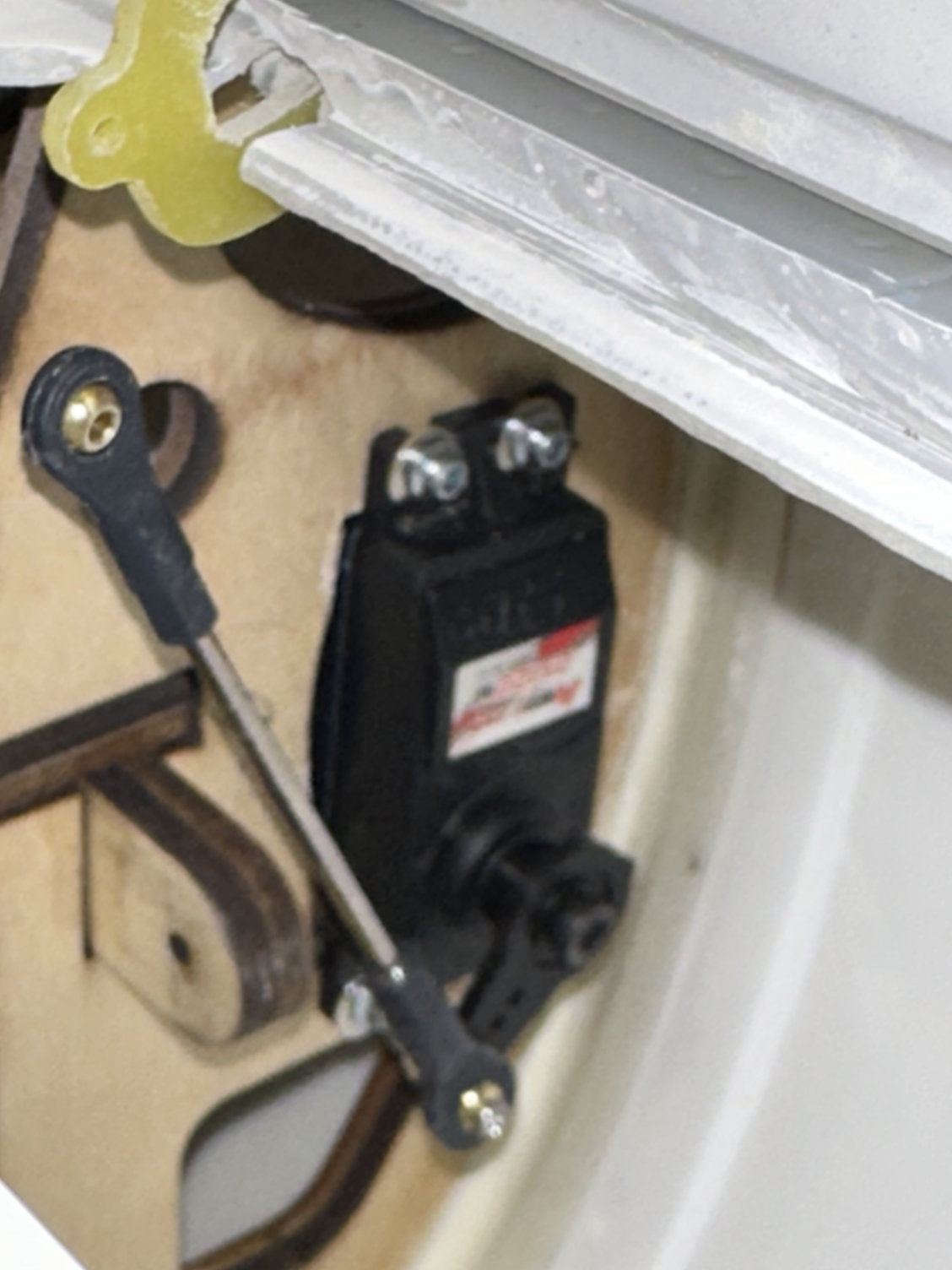
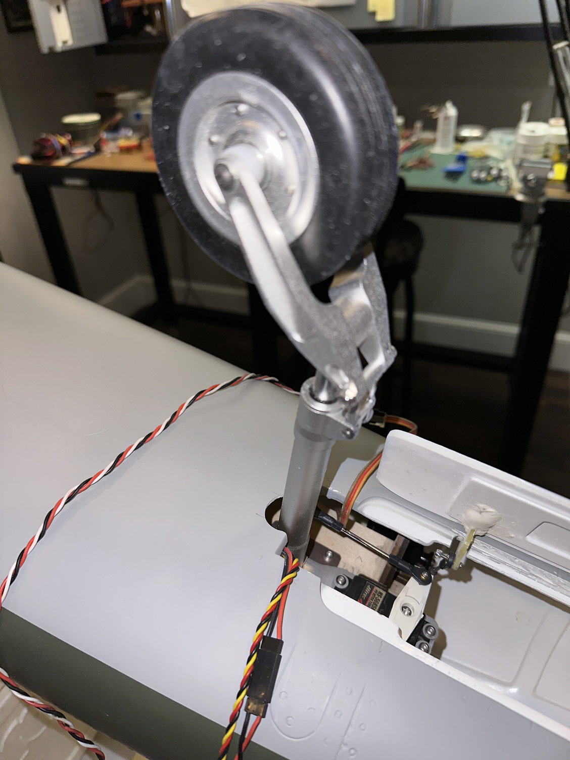
Next up: the nose gear and the next minor challenge of the build as you will see. First, the nose gear door needs to be trimmed slightly to allow it to open all the way and not interfere with the fuselage. Quick work with a Dremel cut-off wheel. Next I mounted the nose door servo. As Cap'n Dave pointed out to me, you can just open up the oval in the bulkhead and place the servo in the opening. I used my Multi-function tool to make the opening rectangular (see pics).
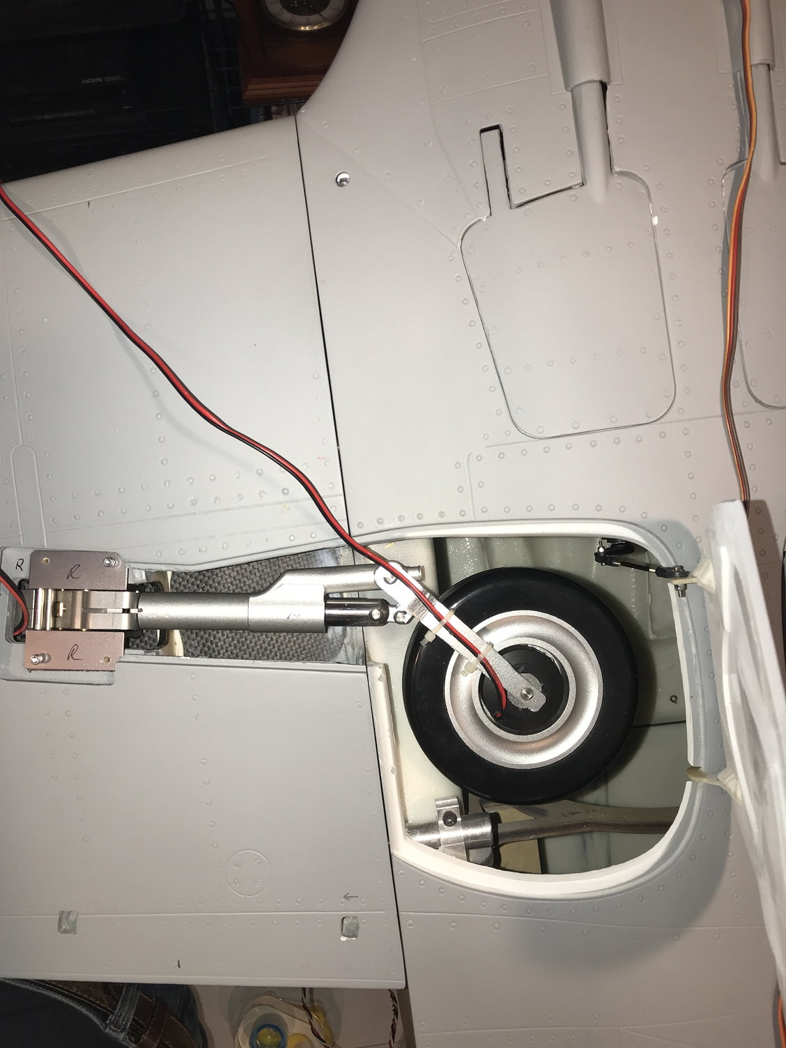
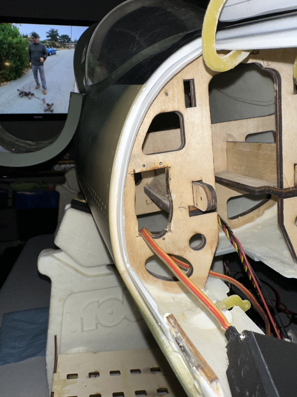
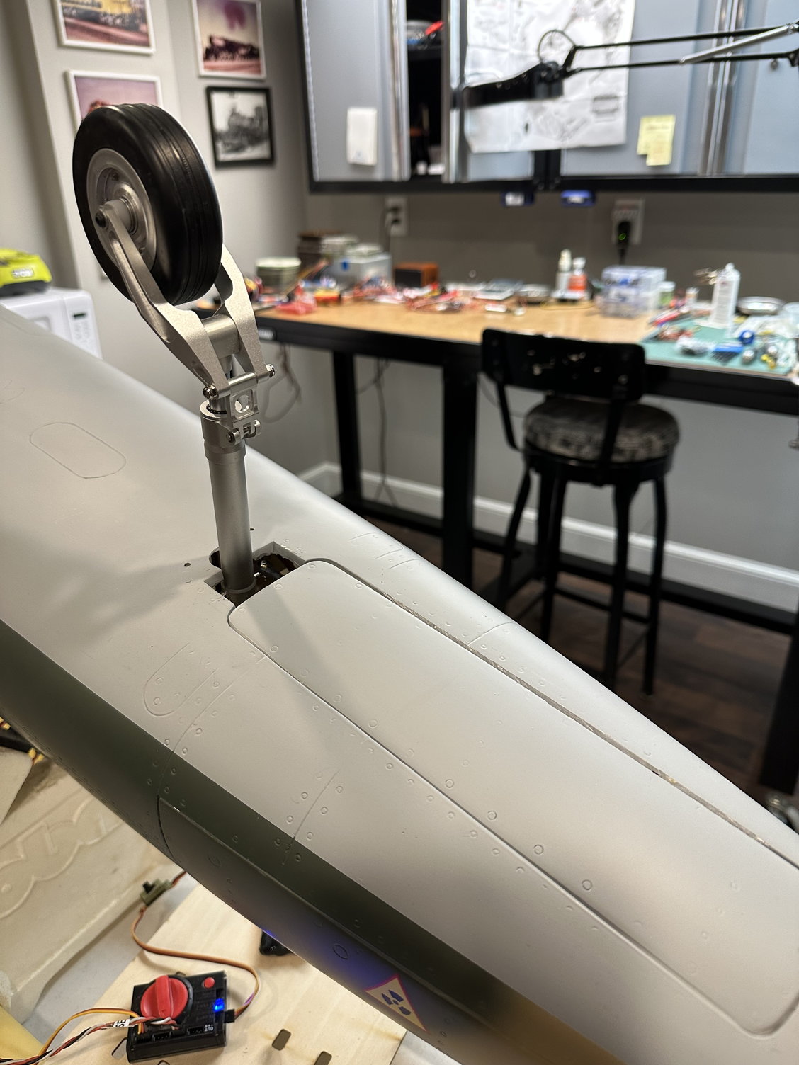
Now for the issue; if you place the nose retract in the down position all the way back so the strut is up against the rear of the opening, you will discover that the wheel will hit the front of the gear door opening. Eddie B. came up with a great solution that is not very invasive and looks OK. His solution was to grind a semicircle at the rear of the opening to accommodate moving the strut / retract rearward (see pics). This allows you to place the wheel in alignment with the relief in the gear door so it can fully close. You will also have to drill two small openings in the fuselage so you can use a ball driver on the two, rear retract mounting holes. Locating the correct placement of the retract will take a little trial and error, but it is not too difficult once you understand it has to be moved rearward so it can operate without hitting the front of the gear door opening.
More later....
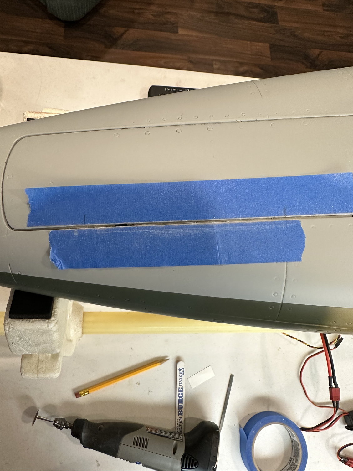
Trimming nose gear door so it can open fully.
Making the rectangular opening in the oval for the nose gear door servo.
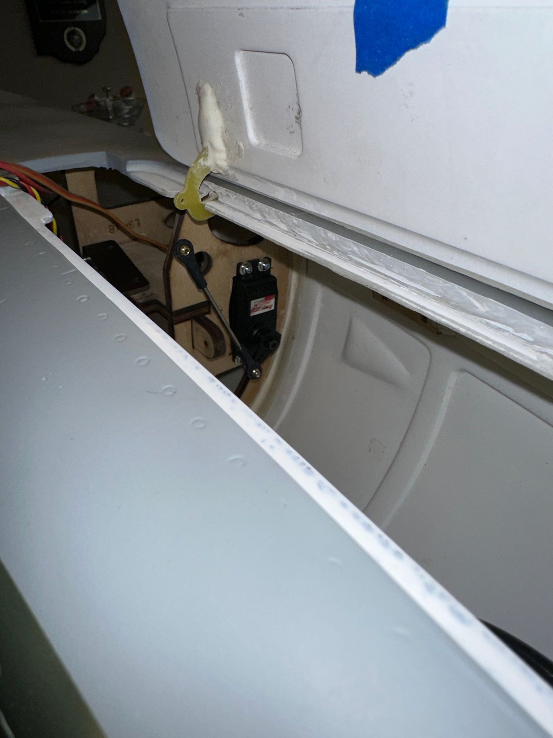
Nose gear door servo mounted.
Nose gear door servo mounted.
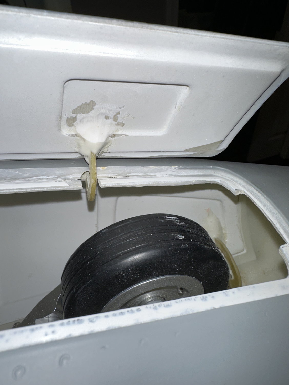
Nose wheel aligned with relief in gear door above so the door will close fully.
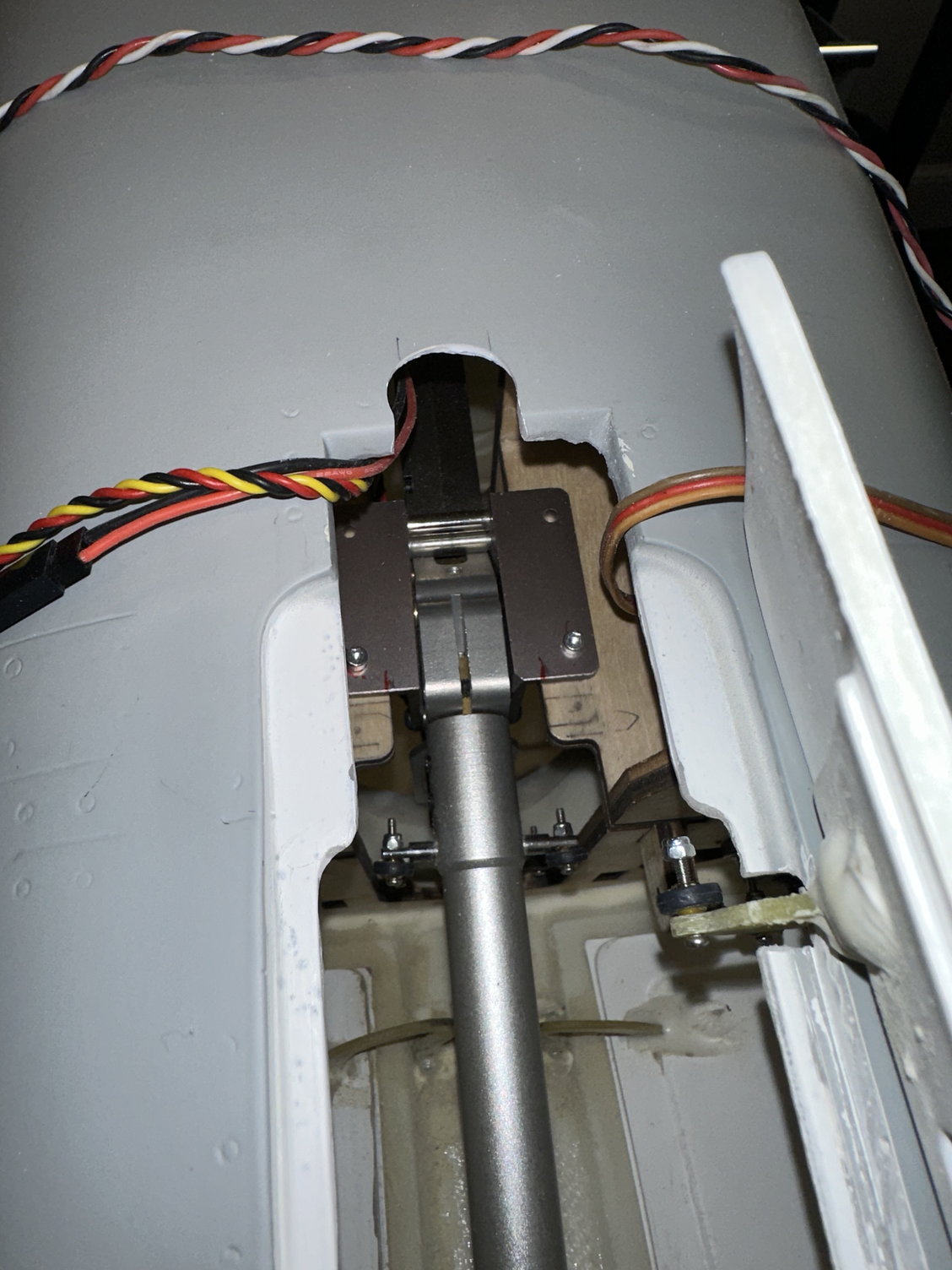
Semicircle relief cut / ground into rear of opening to allow the wheel to clear front of opening.
Semicircle relief cut / ground into rear of opening to allow the wheel to clear front of opening.
Semicircle relief cut / ground into rear of opening to allow the wheel to clear front of opening.
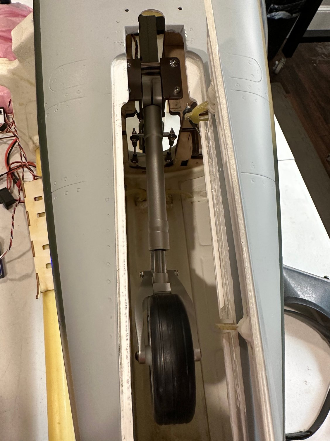
Notice two small holes in fuse near relief to allow use of a ball driver to secure rear of retract.
Now for the issue; if you place the nose retract in the down position all the way back so the strut is up against the rear of the opening, you will discover that the wheel will hit the front of the gear door opening. Eddie B. came up with a great solution that is not very invasive and looks OK. His solution was to grind a semicircle at the rear of the opening to accommodate moving the strut / retract rearward (see pics). This allows you to place the wheel in alignment with the relief in the gear door so it can fully close. You will also have to drill two small openings in the fuselage so you can use a ball driver on the two, rear retract mounting holes. Locating the correct placement of the retract will take a little trial and error, but it is not too difficult once you understand it has to be moved rearward so it can operate without hitting the front of the gear door opening.
More later....
Trimming nose gear door so it can open fully.
Making the rectangular opening in the oval for the nose gear door servo.
Nose gear door servo mounted.
Nose gear door servo mounted.
Nose wheel aligned with relief in gear door above so the door will close fully.
Semicircle relief cut / ground into rear of opening to allow the wheel to clear front of opening.
Semicircle relief cut / ground into rear of opening to allow the wheel to clear front of opening.
Semicircle relief cut / ground into rear of opening to allow the wheel to clear front of opening.
Notice two small holes in fuse near relief to allow use of a ball driver to secure rear of retract.
11-14-2022, 06:41 AM
#35
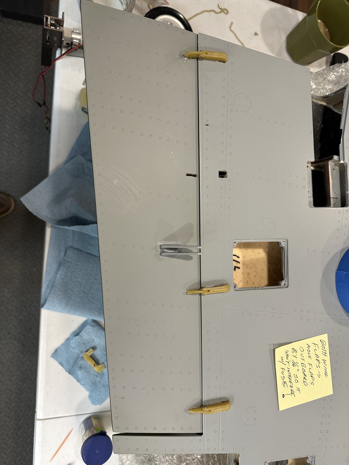
Time to finish the wings: First, the flaps. The four hinges per flap have pre-cut slots in the wing and flaps; a great time saver. On my jet as delivered, the pre-cut slots appeared to place the flaps 1/16" or 1.5mm too far inboard towards the fuselage. In other words, the flaps would interfere / scrape the fuselage if the hinges were just glued into current slots. I chose to slightly widen the slots in both flaps to ensure the flaps would clear the fuselage. The flap control rod on my implementation was 3.5" long (center to center of the ball links). This allows 65mm of down flaps (approximately 37 degrees) as measured at the outboard edge of the flap (see pic). Since at this time there are no published control throws I decided to check other manufacturer's control throws for their L-39s. The 37 degrees appears to be adequate compared to other L-39s. I did paint the hinges grey to match the bottom of the wing.
The aileron control rod for my jet was 3.625" long (center to center of the ball links) which allows for 60mm of throw measured inboard (towards fuselage - see pics). I suspect this will be way more than required.
The last step was to clean the short aluminum wing mounting tubes with alcohol and Hysol them into each wing. Saving the tip tanks for later since I need to mount the spot lights and Nav / ACL lights.
More later......
Test fitting of hinges - see text
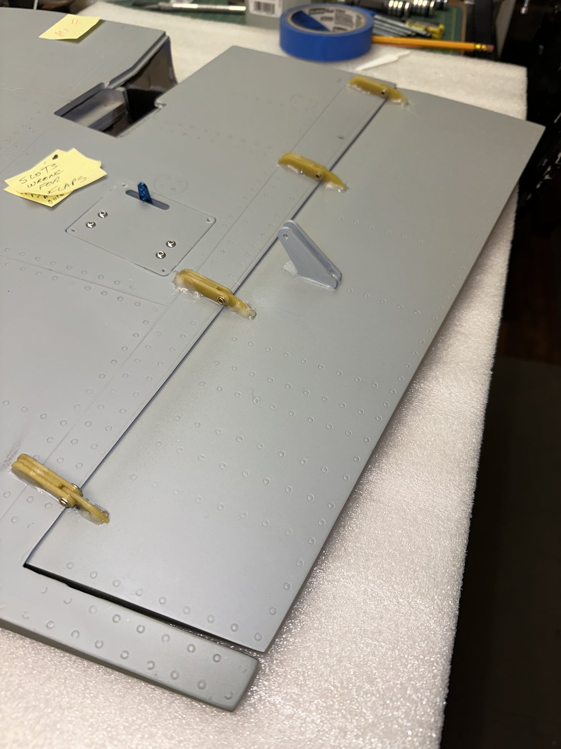
Test fitting of hinges - see text
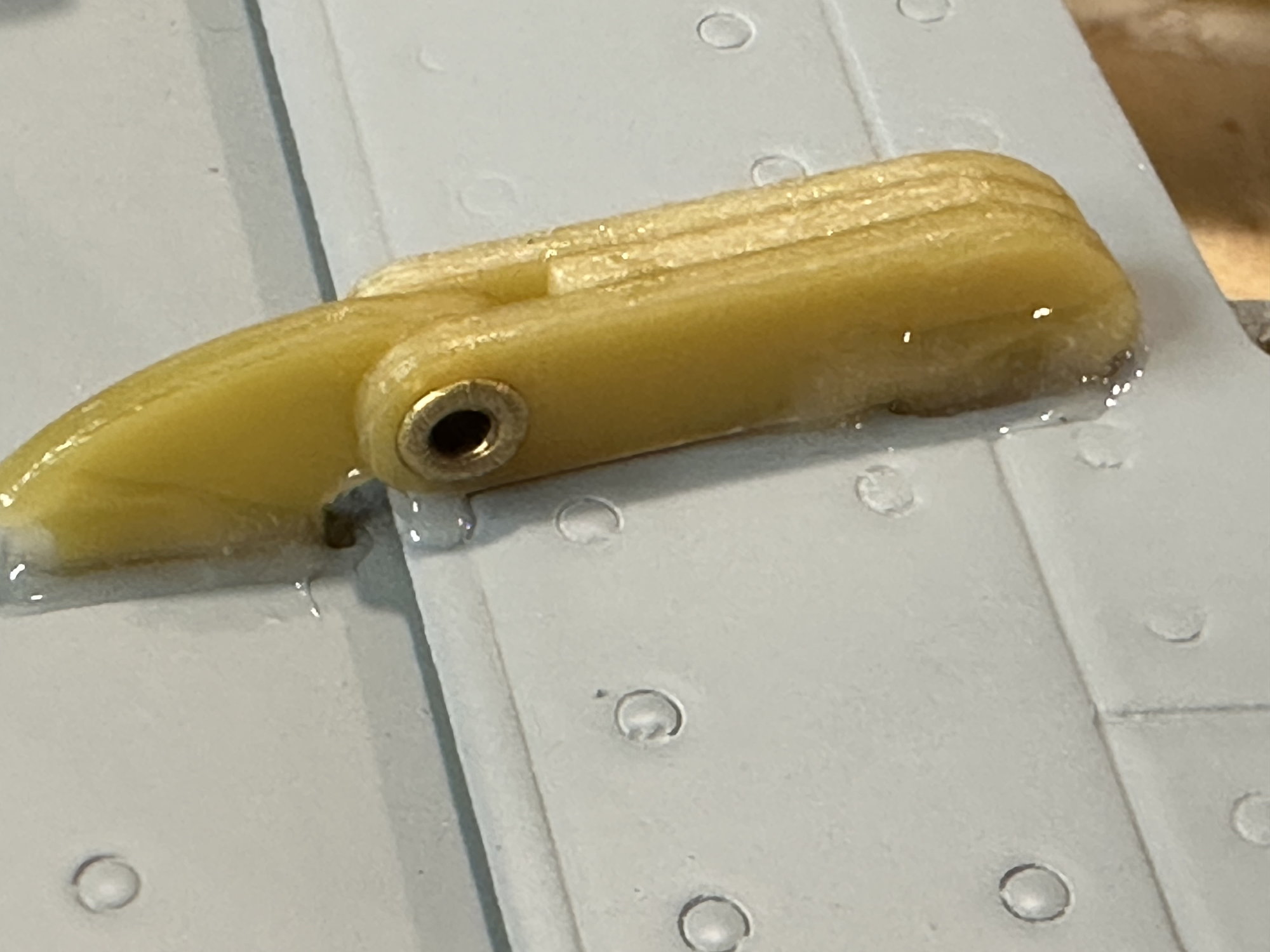
Closeup of hinge epoxied with BVM QT Plus.
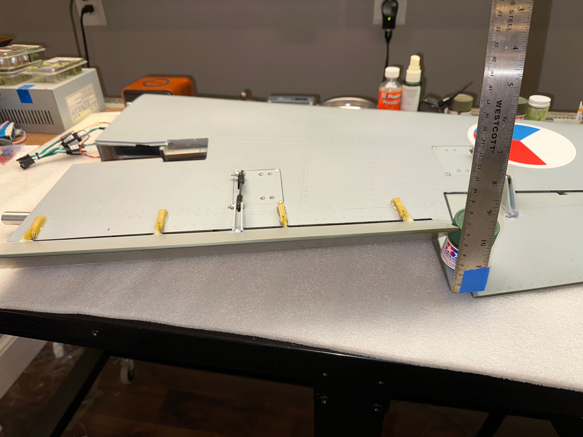
Flap throw measured at outboard location
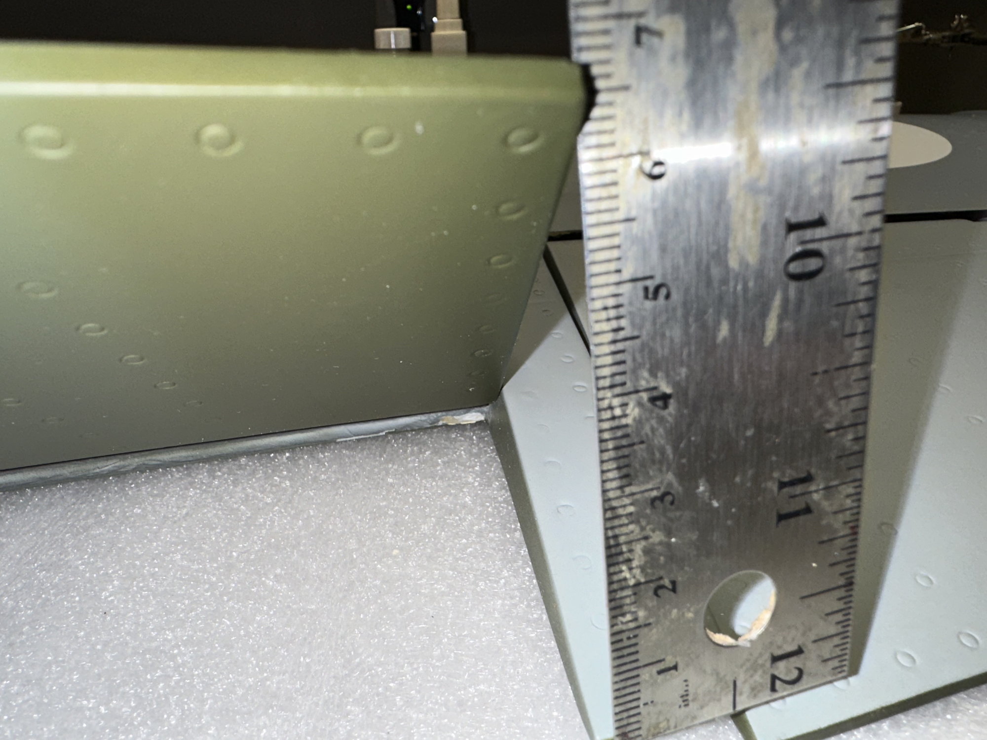
Flap throw measured at outboard location
Aileron control linkage
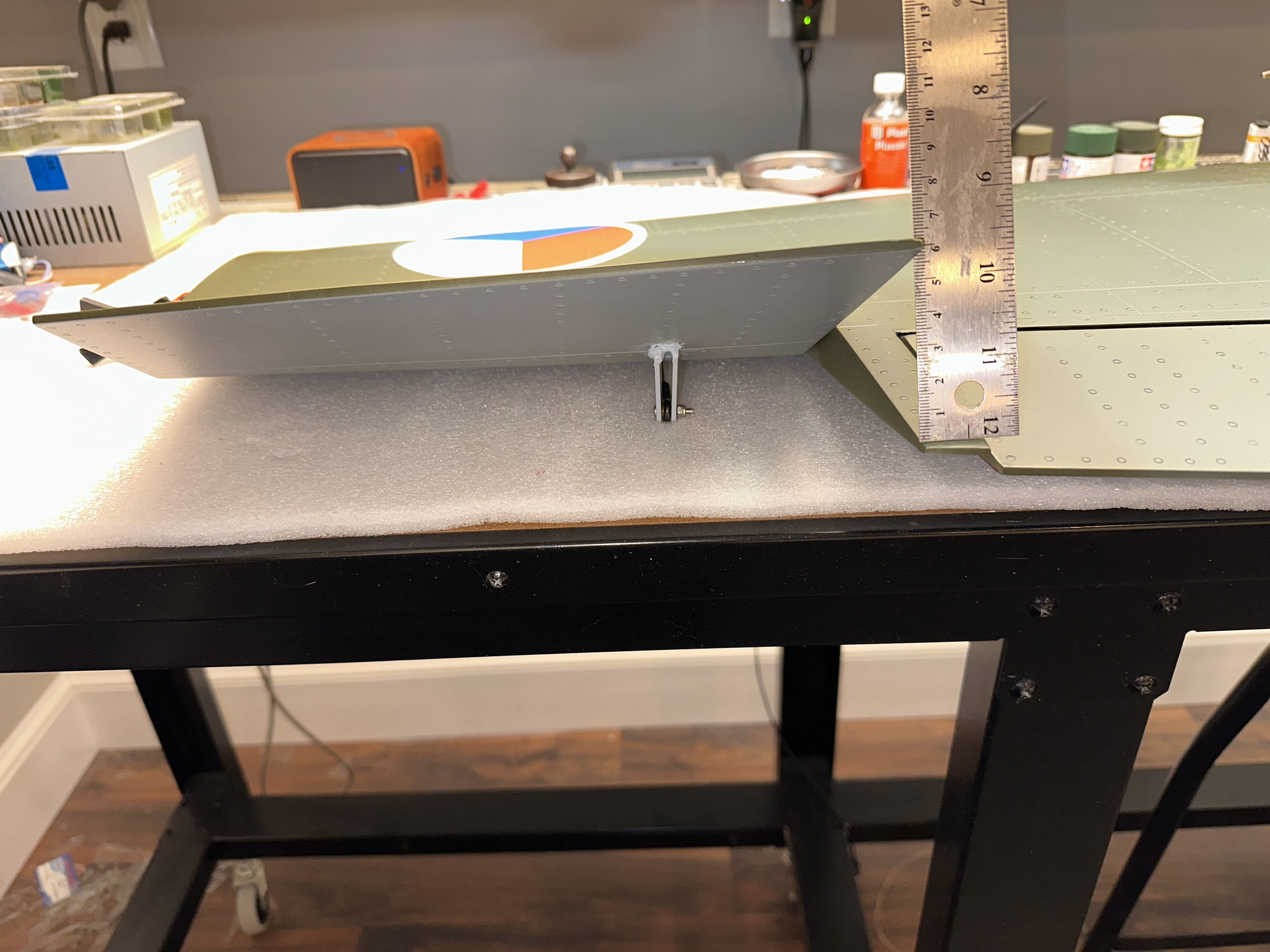
Aileron throw measured at inboard location
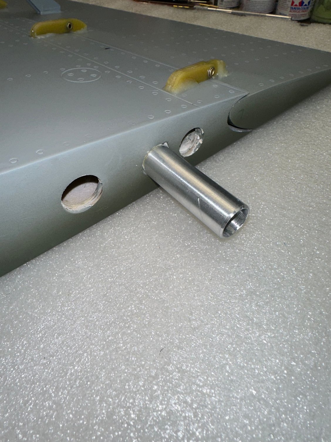
Short aluminum wing mounting tube epoxied into wing.
The aileron control rod for my jet was 3.625" long (center to center of the ball links) which allows for 60mm of throw measured inboard (towards fuselage - see pics). I suspect this will be way more than required.
The last step was to clean the short aluminum wing mounting tubes with alcohol and Hysol them into each wing. Saving the tip tanks for later since I need to mount the spot lights and Nav / ACL lights.
More later......
Test fitting of hinges - see text
Test fitting of hinges - see text
Closeup of hinge epoxied with BVM QT Plus.
Flap throw measured at outboard location
Flap throw measured at outboard location
Aileron control linkage
Aileron throw measured at inboard location
Short aluminum wing mounting tube epoxied into wing.
11-16-2022, 02:54 AM
#36

I have started my very first vlog build with the TopRC L-39. Cap'n Dave Murray has his fingerprints on this build as well. Your thread is very helpful.
Please take a look at my unboxing video:
I would appreciate your comments and suggestions as I move forward.
Please take a look at my unboxing video:
The following 2 users liked this post by rjmonroe:
knuckleball (11-16-2022),
Nick Yuhasz (11-16-2022)
11-21-2022, 03:52 PM
#38
I used thread with a small fishing lead weight on the end to "fish" it through from the top of the fin where the strobe will go to the base. Yes, it took a very, very long time. I tilted the fin and tried to get it to flow through holes towards the fin leading edge. Since Post #16 where Clay suggested using a light pull chain, I have been using that method - seems to work better than my thread / lead weight method. Good luck!
Nick
Nick
The following users liked this post:
gui8 (12-05-2022)
12-03-2022, 09:45 AM
#43
Bye!
I've ordered the L39 for a week but unfortunately it's imported into Italy twice a year and I'll have to wait until April to get my hands on it.
I am following with great interest your post which will be very useful to me when I start the work
Francis
I've ordered the L39 for a week but unfortunately it's imported into Italy twice a year and I'll have to wait until April to get my hands on it.
I am following with great interest your post which will be very useful to me when I start the work
Francis
Clay: Thanks for the tip on the "pull chain"! I will try that for the wing nav / ACL lighting wire.
So for all of my large jets, I perform a servo torque requirement calculation that is contained in the AMA Large Turbine Model program (I don't anticipate that this jet will need to be a LTMA jet).
Based on those calculations for an "unlimited aerobatic" jet traveling > 140 mph, here are the minimum servo torque requirements for the TopRC L-39:
Aileron - 256 oz. / in.
Elevator - 203 oz. / in
Rudder - 206 oz. / in
These calculations are based on the control surface's length, root and tip chord plus the servo arm length and control horn length. At first blush, the rudder torque seems too low for such a large fin, but the actual rudder is small compared to the aileron area. Remember these are minimums.
More later.........
12-18-2022, 06:36 PM
#44
Back in Ohio again so on to mounting main switches / charging jacks and A123 batteries.
I decided to mount the two receiver power switches, the lighting / smoke pump switch, and the retract / brake power switch to be accessed through the full scale access hatch in the nose. No need to open the cockpit canopies to charge batteries or power up the aircraft or start the turbine. This also allows two A123 receiver batteries to be mounted all the way forward in the nose (see pic). Two A123 batteries for lights and retracts to be mounted on the right side and just aft of the nose retract mount and the 3 cell A123 ECU battery on the left side and just aft of the nose retract mount. That is almost 2.5 pounds of batteries far forward to help with balance / CG. All batteries held in place with Velcro.
More later……..
Four primary switches mounted in nose.
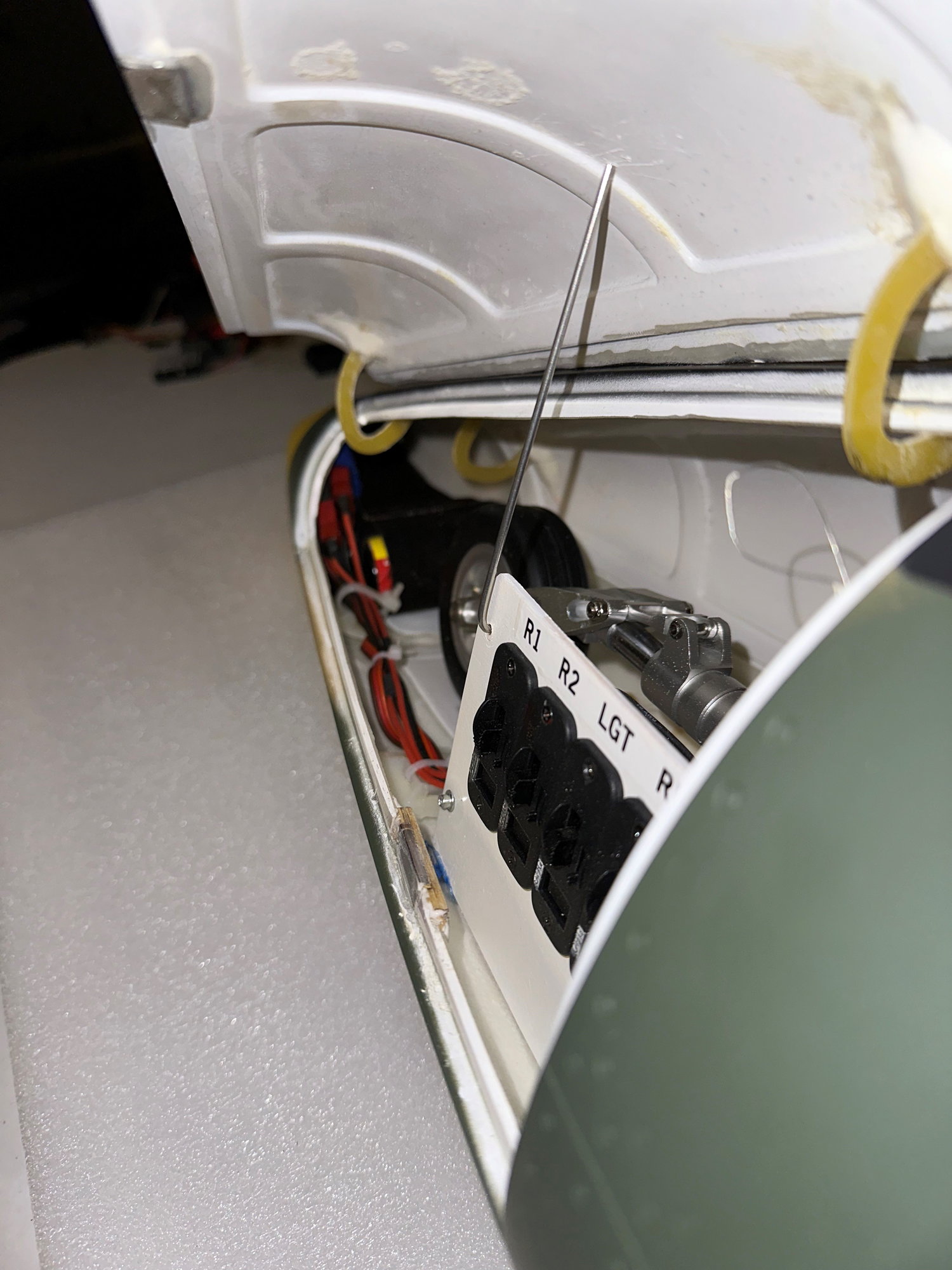
Two A123 receiver batteries all the way forward in the nose.
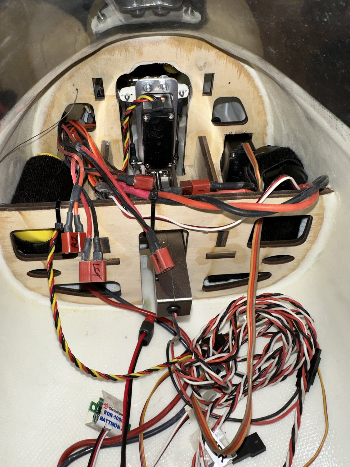
Lighting and retract A123 batteries mounted on the right just aft of the nose retract bulkhead.
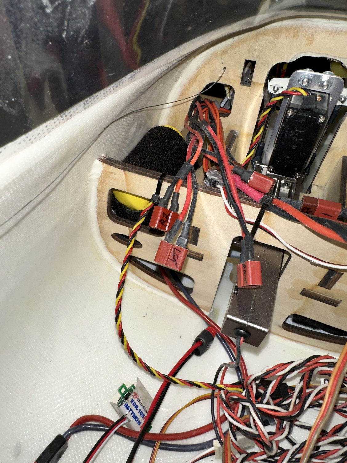
ECU A123 3 cell battery on left.
I decided to mount the two receiver power switches, the lighting / smoke pump switch, and the retract / brake power switch to be accessed through the full scale access hatch in the nose. No need to open the cockpit canopies to charge batteries or power up the aircraft or start the turbine. This also allows two A123 receiver batteries to be mounted all the way forward in the nose (see pic). Two A123 batteries for lights and retracts to be mounted on the right side and just aft of the nose retract mount and the 3 cell A123 ECU battery on the left side and just aft of the nose retract mount. That is almost 2.5 pounds of batteries far forward to help with balance / CG. All batteries held in place with Velcro.
More later……..
Four primary switches mounted in nose.
Two A123 receiver batteries all the way forward in the nose.
Lighting and retract A123 batteries mounted on the right just aft of the nose retract bulkhead.
ECU A123 3 cell battery on left.
12-21-2022, 05:43 PM
#45
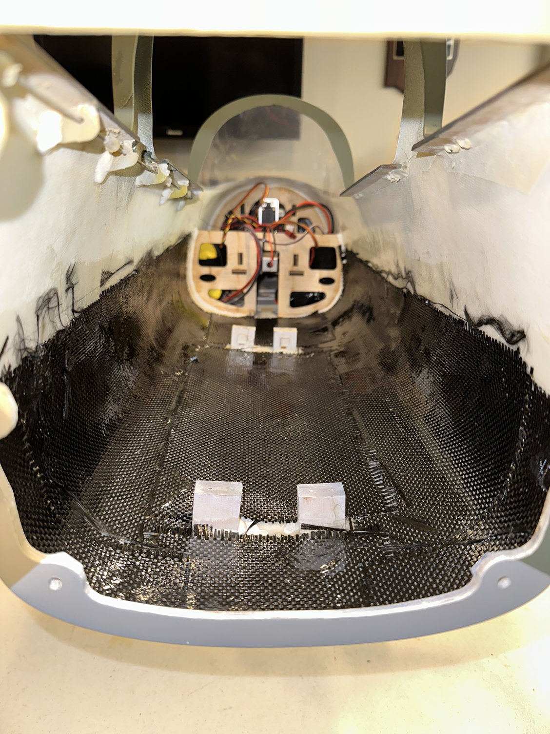
The next task I decided to do may be controversial. I decided to strengthen the area under the canopy with carbon fiber cloth that I had.
There is a 2 foot section, under the canopies, between the rear portion of the front fuselage bulkhead and the bulkhead at the front where the nose retract is mounted where there are no bulkheads; only lightweight fiberglass walls / sides and bottom fuse. With all the weight I added to balance far forward, I felt this open section could be a weak spot on the fuselage if there were to be a less than perfect landing or after performing a high stress aerobatic maneuver. After adding the CF cloth using West Systems finishing epoxy, I only added 6 oz. of weight (see pics). The extra weight ahead of the CG was acceptable in my opinion for some peace of mind.
More later……..
Nick
View of CF cloth added from the rear of the front fuse section
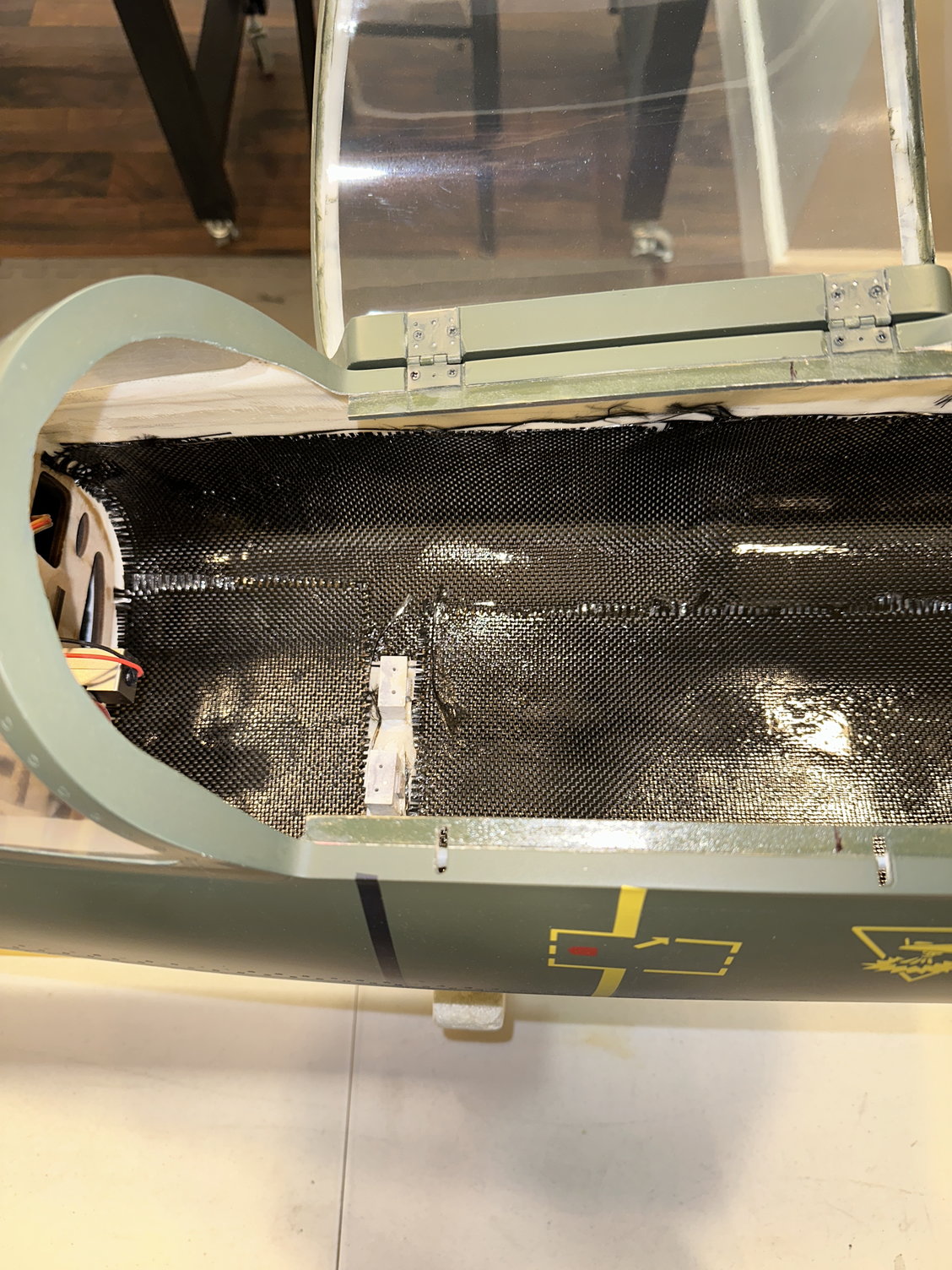
View of CF cloth added from the top of the front fuse section
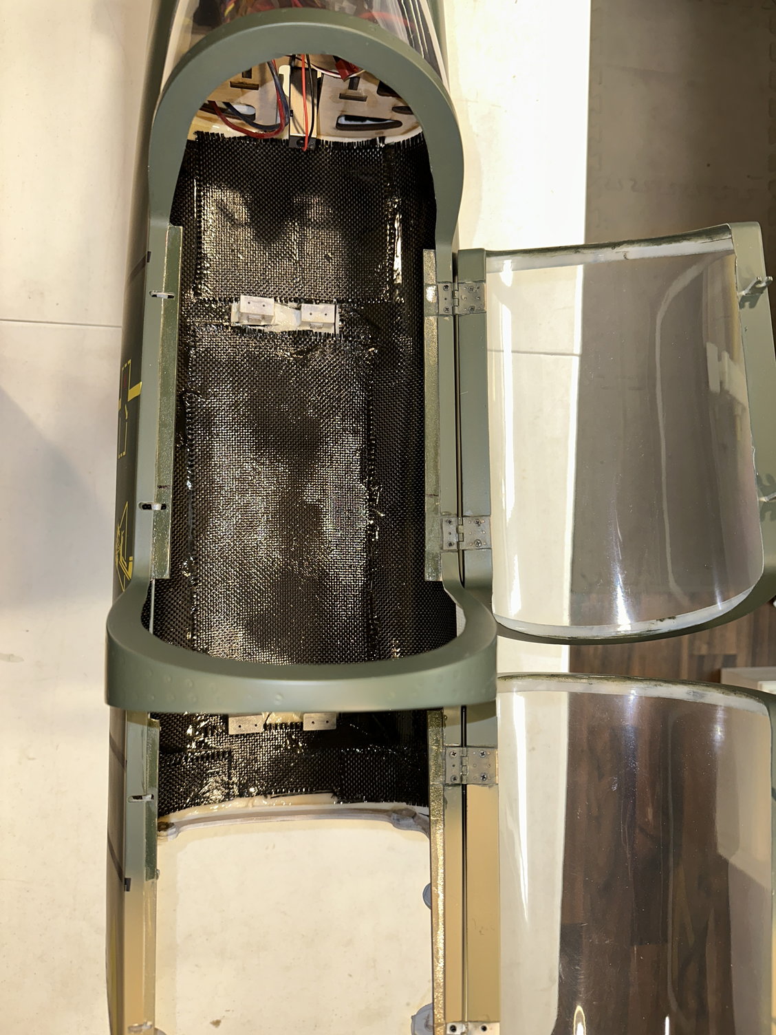
View of CF cloth added from the top of the front fuse section
There is a 2 foot section, under the canopies, between the rear portion of the front fuselage bulkhead and the bulkhead at the front where the nose retract is mounted where there are no bulkheads; only lightweight fiberglass walls / sides and bottom fuse. With all the weight I added to balance far forward, I felt this open section could be a weak spot on the fuselage if there were to be a less than perfect landing or after performing a high stress aerobatic maneuver. After adding the CF cloth using West Systems finishing epoxy, I only added 6 oz. of weight (see pics). The extra weight ahead of the CG was acceptable in my opinion for some peace of mind.
More later……..
Nick
View of CF cloth added from the rear of the front fuse section
View of CF cloth added from the top of the front fuse section
View of CF cloth added from the top of the front fuse section
12-22-2022, 12:12 PM
#46
Here is a picture of the main control board containing one of the two receivers, the iGyro SRS, the Unilight controller, and the TopRC retract / brake controller. I will add the 2nd receiver and the iGyro GPS after I join the two halves of the fuselage and finish all the wiring to the various control units.
I want to thank Clay for reminding me of the Peel Ply product which would have saved me some weight in removing excess epoxy resin from the carbon fiber cloth. I will utilize Peel Ply again in the future.
Next up: Joining the front and back fuselage halves! Finally, the end is in sight!
More later…….
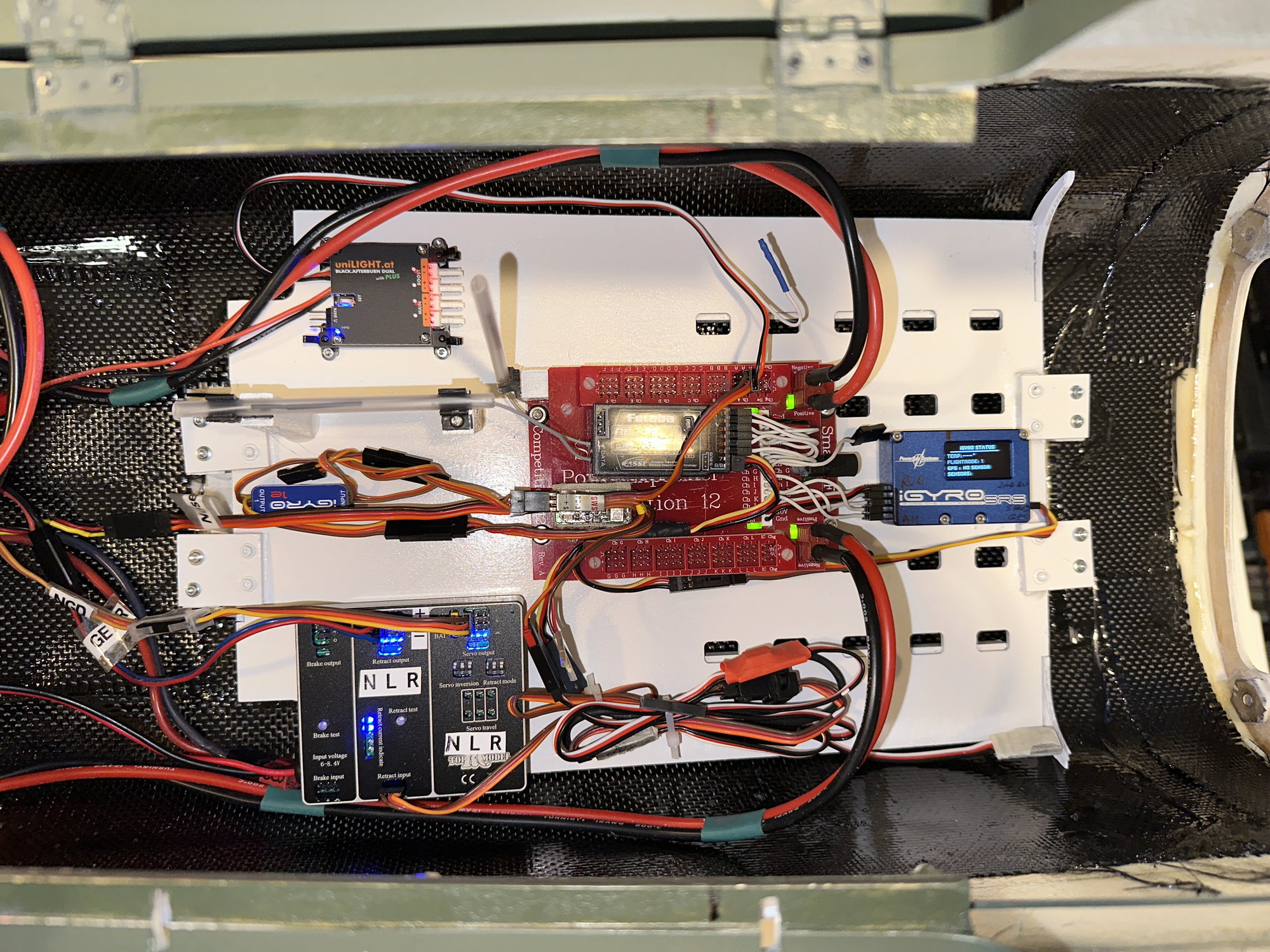
Main control board under cockpit.
I want to thank Clay for reminding me of the Peel Ply product which would have saved me some weight in removing excess epoxy resin from the carbon fiber cloth. I will utilize Peel Ply again in the future.
Next up: Joining the front and back fuselage halves! Finally, the end is in sight!
More later…….
Main control board under cockpit.
12-23-2022, 05:11 AM
#49
My Feedback: (1)
Hi,
I did the same carbon fiber reinforcement to my small Wizard. The space between the front gear mount and the next bulk head was a major weak spot. The carbon 'bath tube' did the trick.
To avoid reception issues - I used two receivers with two antennas each. One pair went all the way in the nose, where there is no carbon. The other ones are between the carbon and turbine. My signal strength proved to be excellent. (I use Jeti in clone mode).
The following 2 users liked this post by jvaliensi:
gui8 (12-24-2022),
Nick Yuhasz (01-02-2023)
12-27-2022, 04:46 PM
#50
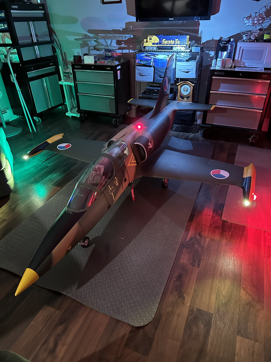
Decided to mount the tip tank Unilights (spotlight, nav light, and ACL). The internal structure of the tip tanks make routing the wiring easy. I used ZAP Goo to mount the light fixtures in the odd chance I would ever need to remove them.
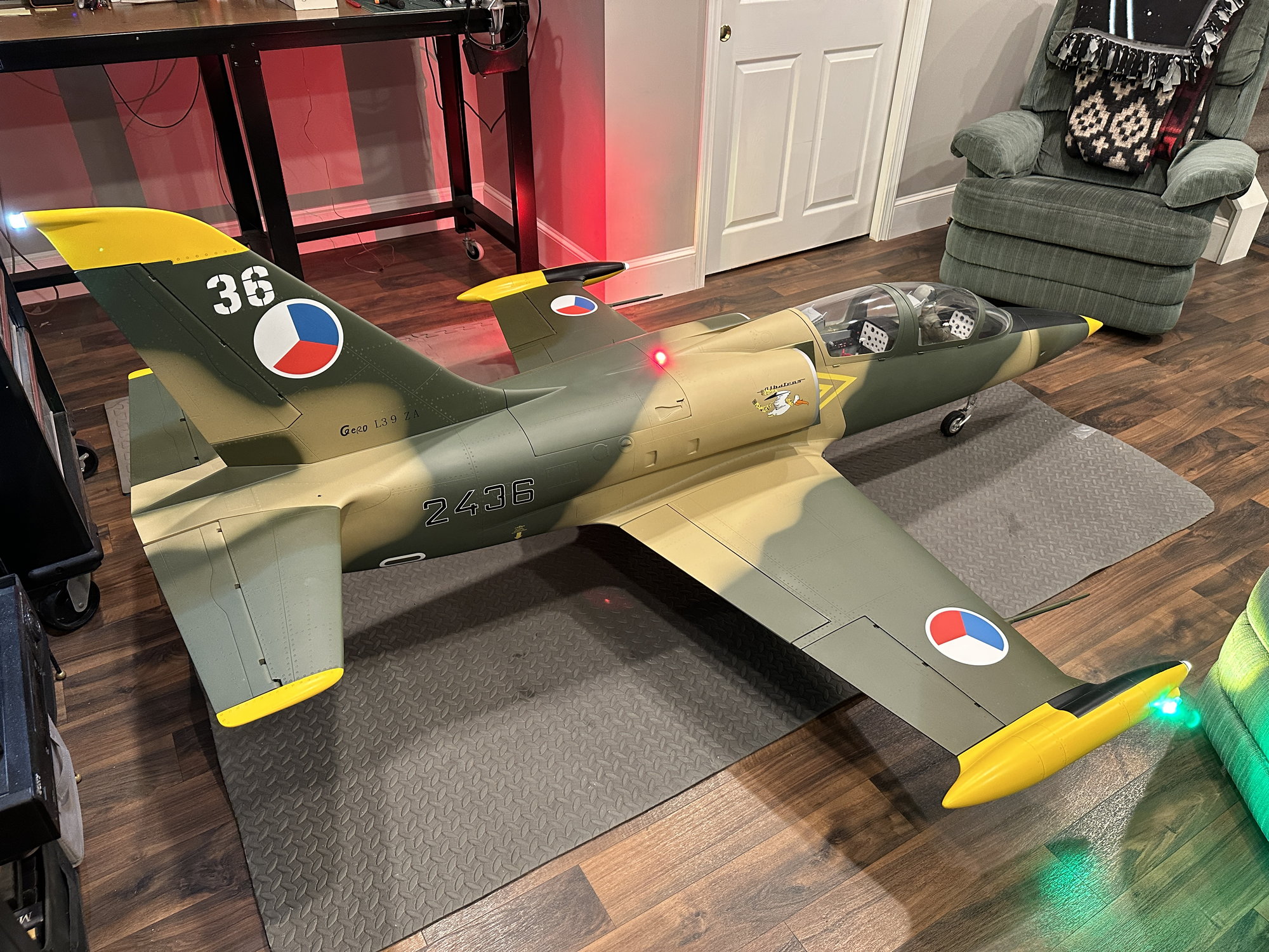
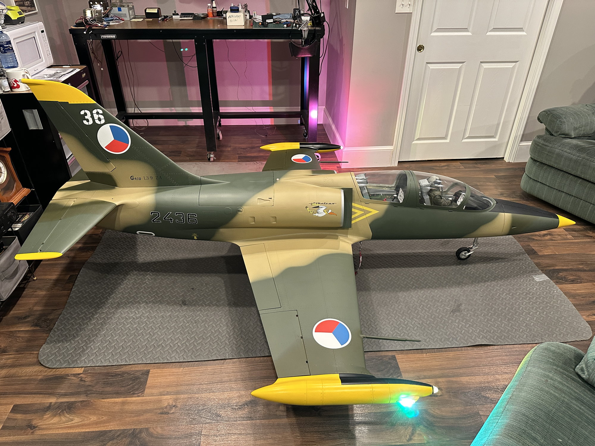
I also made a filler for the space between the front and rear fuselage halves and painted it. See Pic. I installed a Warbird Pilots jet pilot in the front cockpit.
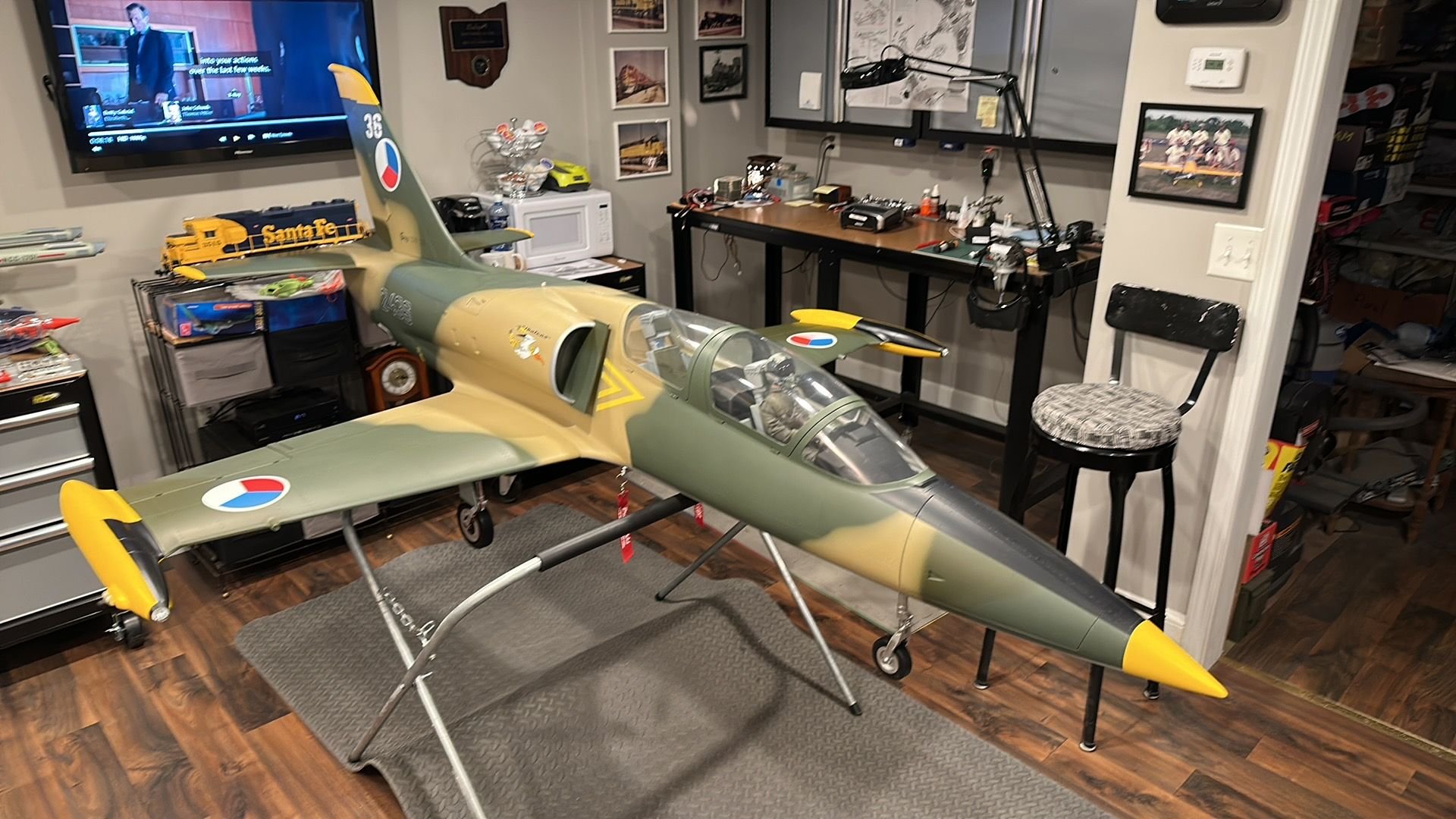
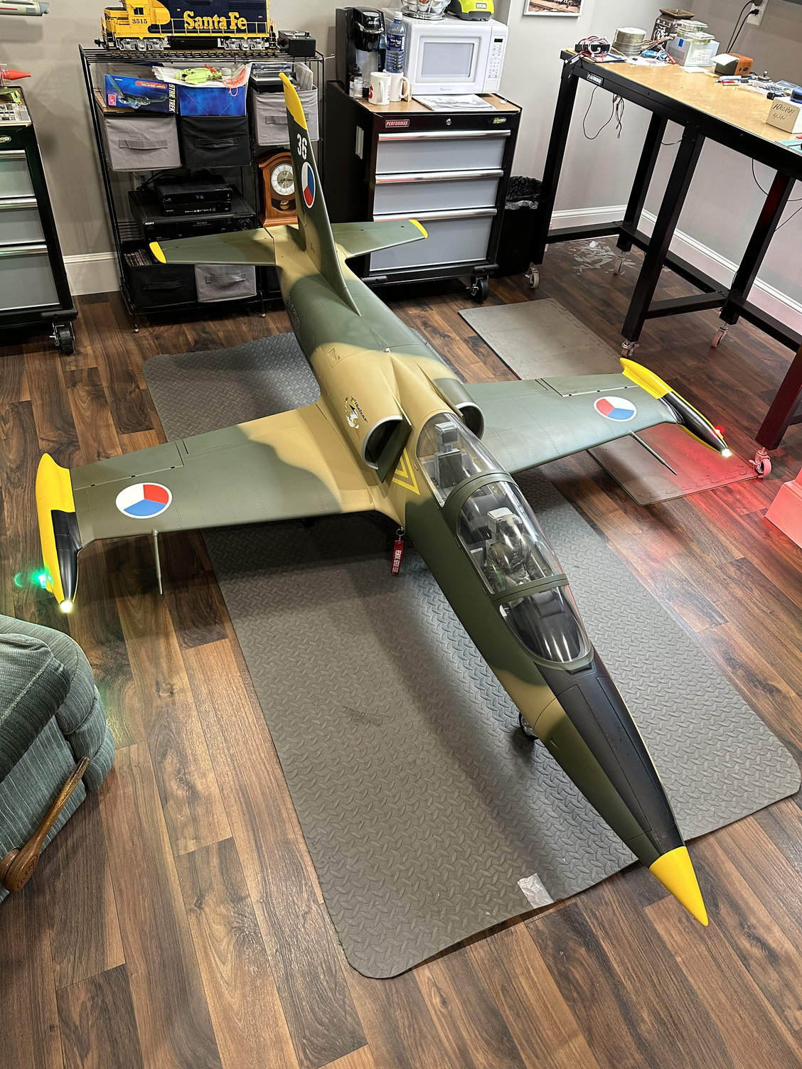
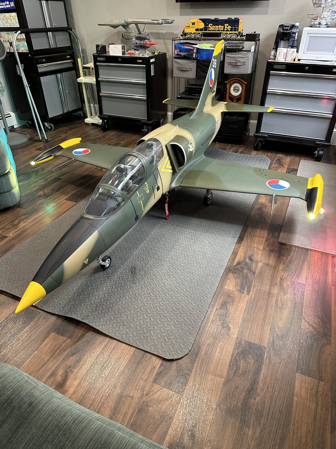
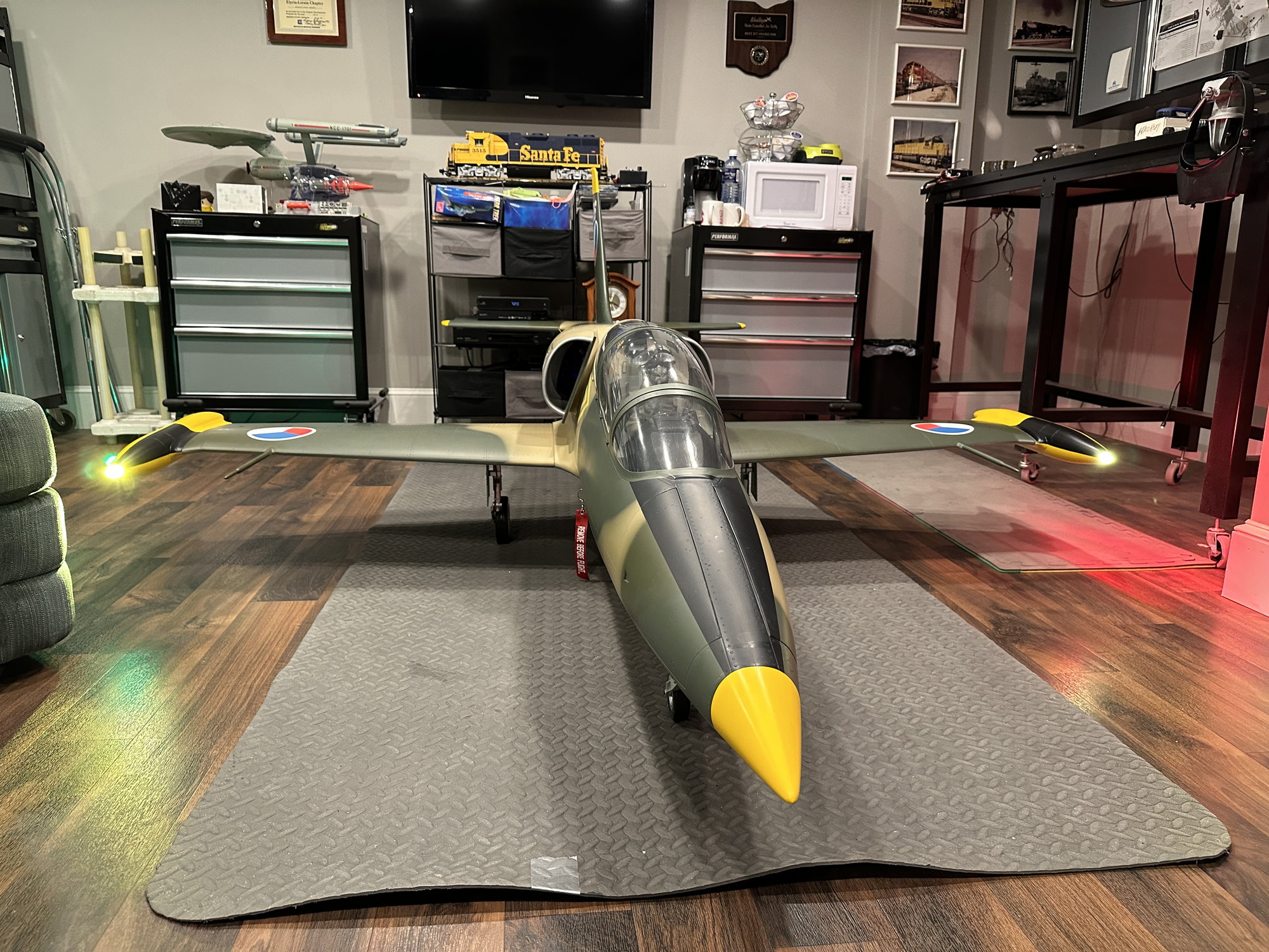
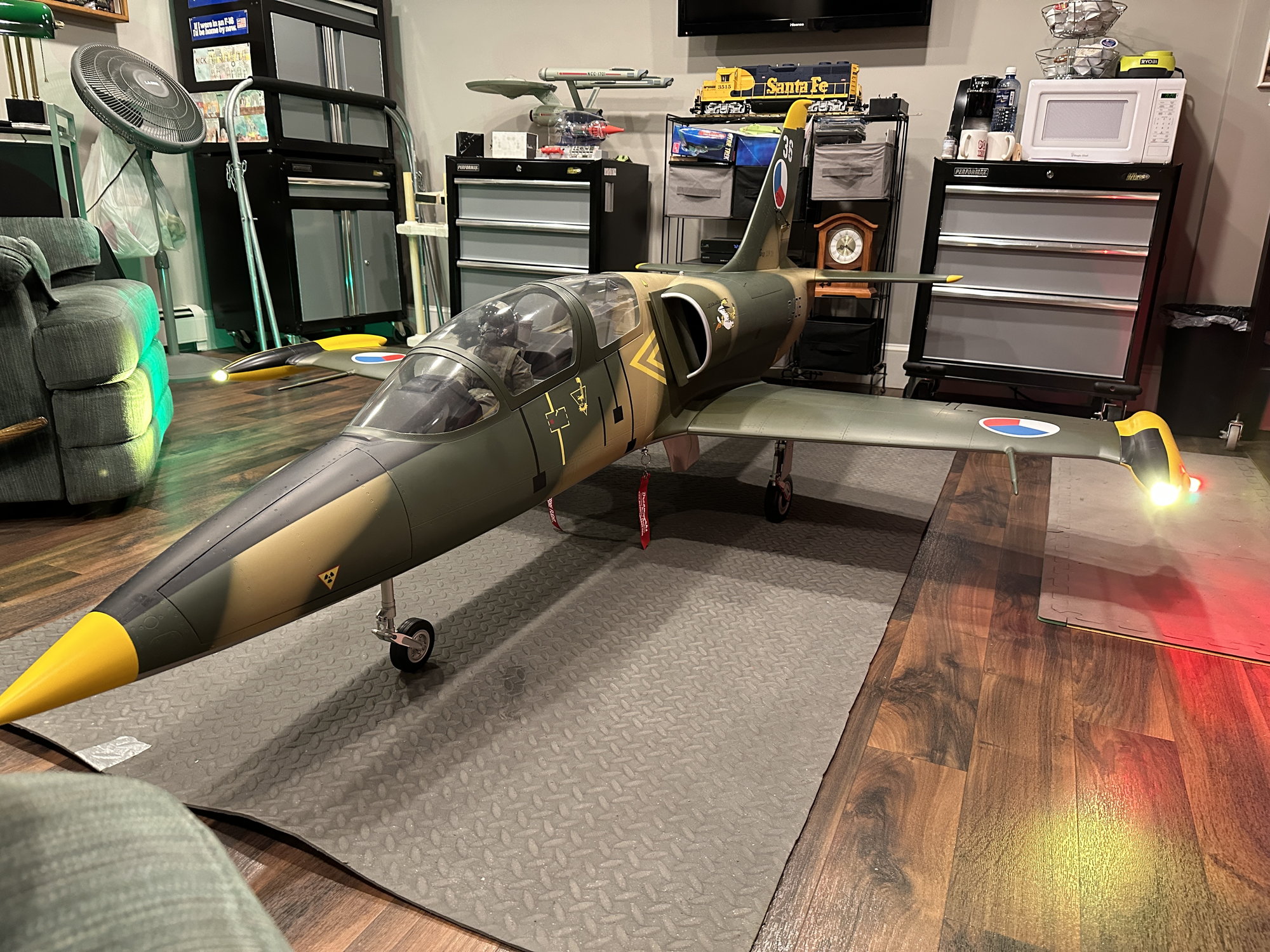
And finally, the assembled TopRC L-39! So, my build / assembly is coming in at 43.5 pounds dry (only UAT full). Keep in mind this is with lighting, a smoke system, and associated A123 batteries included plus the 6 oz of CF cloth and resin under the cockpit area. I am calculating with the fuel tank full of Jet-A, the L-39 will weigh 51 pounds at take-off.
I also am slightly nose heavy per the XiCoy CG Meter at 179mm CG so I may be moving one battery pack further back in the front section of the fuselage.
One other observation that Steven Reeps and I discovered: the large vertical fin clamp in the fuse and the ply below it with a hole to accept the rudder aluminum tube appear to be loose and allow the vertical fin to rock side to side. We suggest you check yours and Hysol / epoxy them if yours exhibits the same behavior.
Well, that is all for now. Temperatures in the teens and snow on the ground in northern Ohio so the range check and maiden flight will have to wait until Spring time. If anyone has proven control throws, please feel free to post them. Thanks for reading my thread and I welcome any questions you may have!
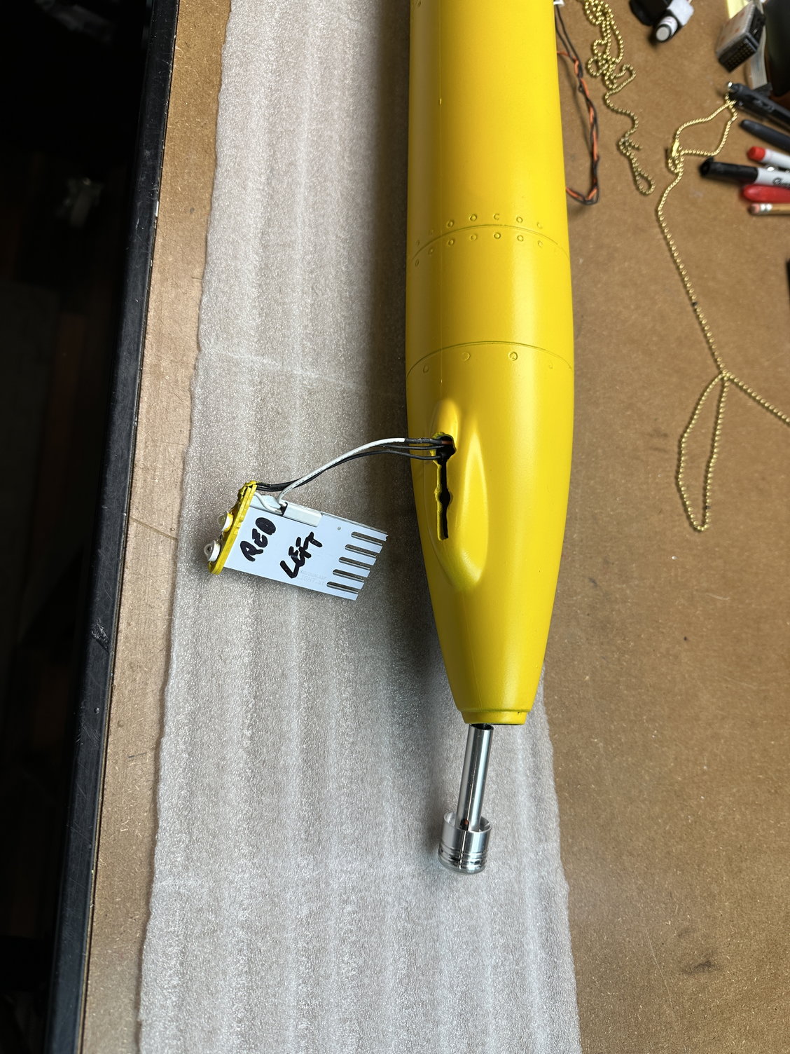
Unilights ready to install
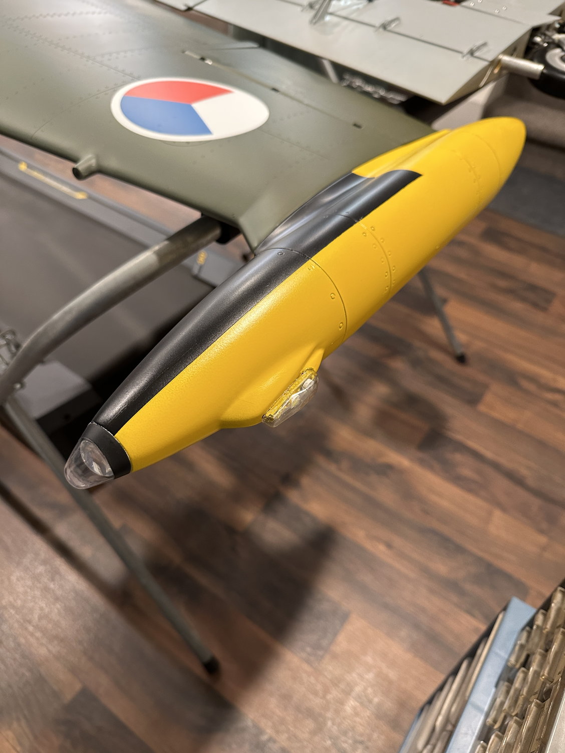
Top of tip tank
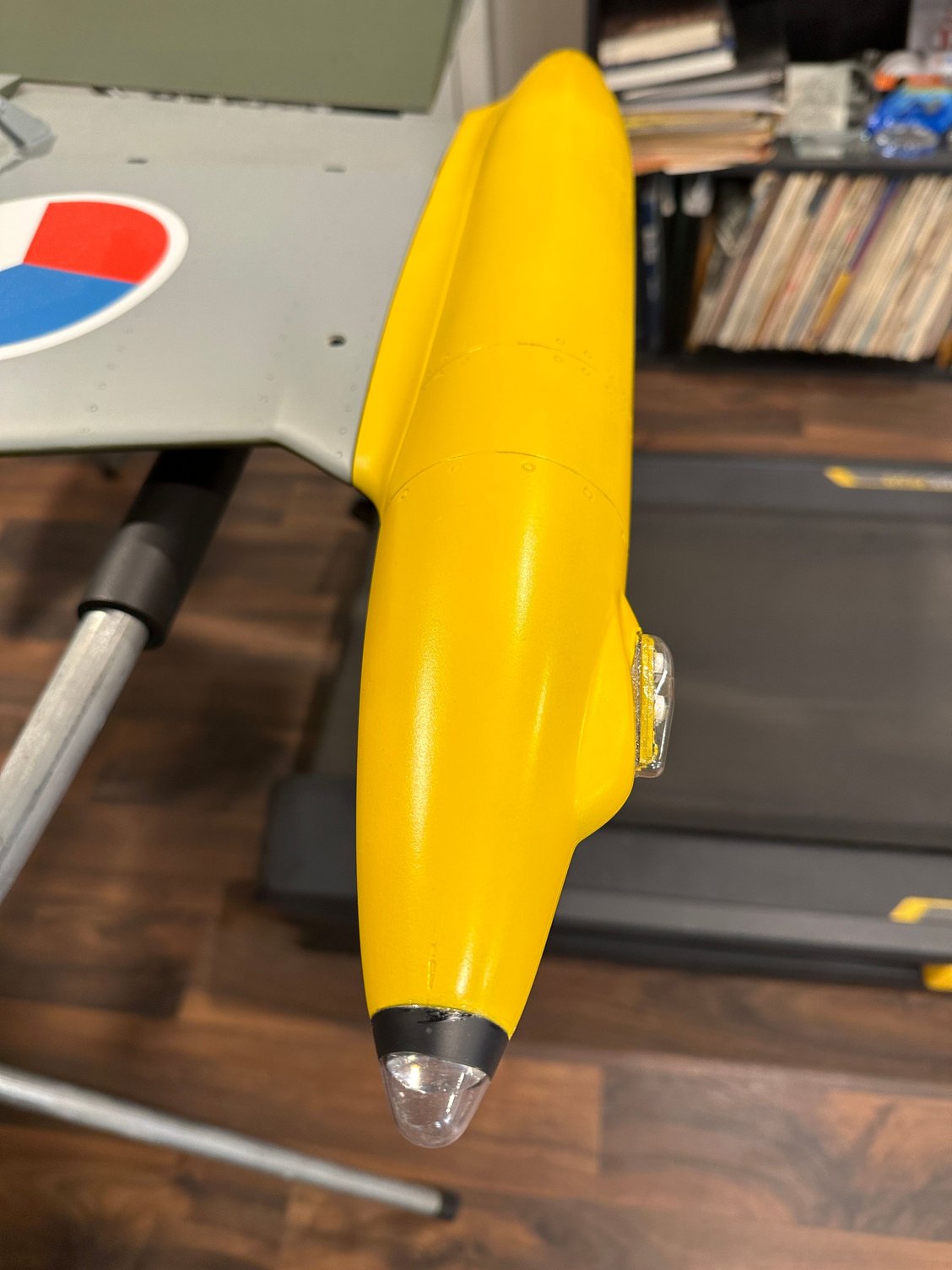
Bottom of tip tank
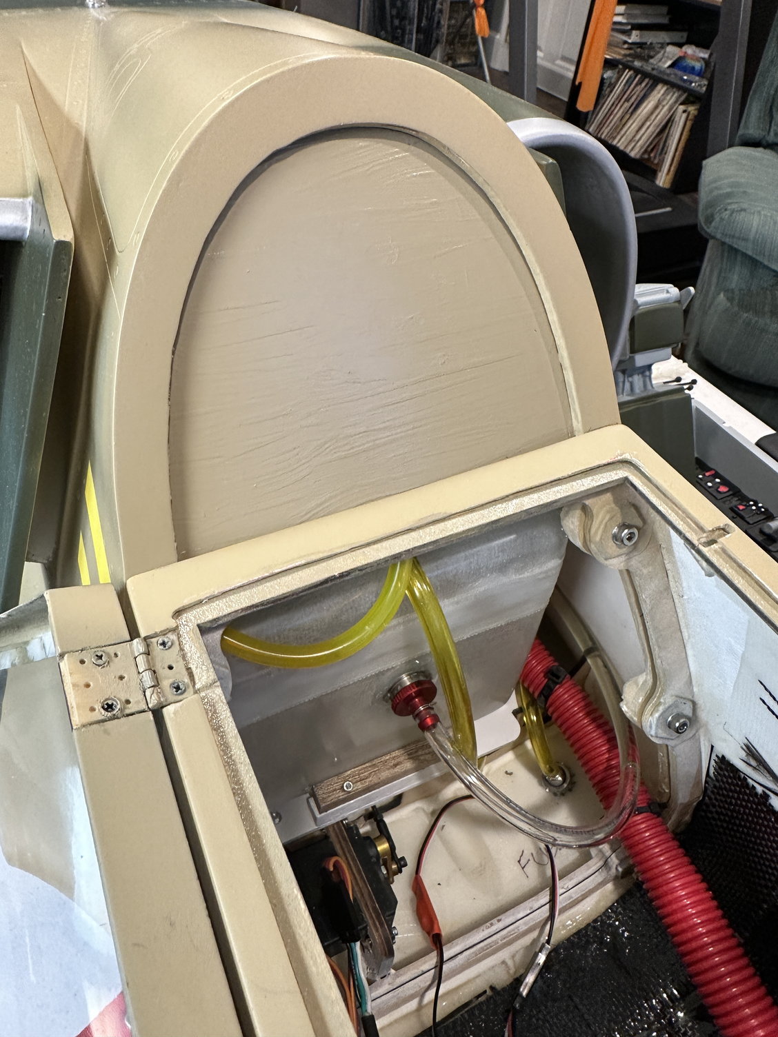
Partition above fuel tank between fuse halves installed
I also made a filler for the space between the front and rear fuselage halves and painted it. See Pic. I installed a Warbird Pilots jet pilot in the front cockpit.
And finally, the assembled TopRC L-39! So, my build / assembly is coming in at 43.5 pounds dry (only UAT full). Keep in mind this is with lighting, a smoke system, and associated A123 batteries included plus the 6 oz of CF cloth and resin under the cockpit area. I am calculating with the fuel tank full of Jet-A, the L-39 will weigh 51 pounds at take-off.
I also am slightly nose heavy per the XiCoy CG Meter at 179mm CG so I may be moving one battery pack further back in the front section of the fuselage.
One other observation that Steven Reeps and I discovered: the large vertical fin clamp in the fuse and the ply below it with a hole to accept the rudder aluminum tube appear to be loose and allow the vertical fin to rock side to side. We suggest you check yours and Hysol / epoxy them if yours exhibits the same behavior.
Well, that is all for now. Temperatures in the teens and snow on the ground in northern Ohio so the range check and maiden flight will have to wait until Spring time. If anyone has proven control throws, please feel free to post them. Thanks for reading my thread and I welcome any questions you may have!
Unilights ready to install
Top of tip tank
Bottom of tip tank
Partition above fuel tank between fuse halves installed
The following users liked this post:
Viper1GJ (01-02-2023)

