


Reaction 54 Jet Kit

 06-20-2018, 03:29 PM
#4077
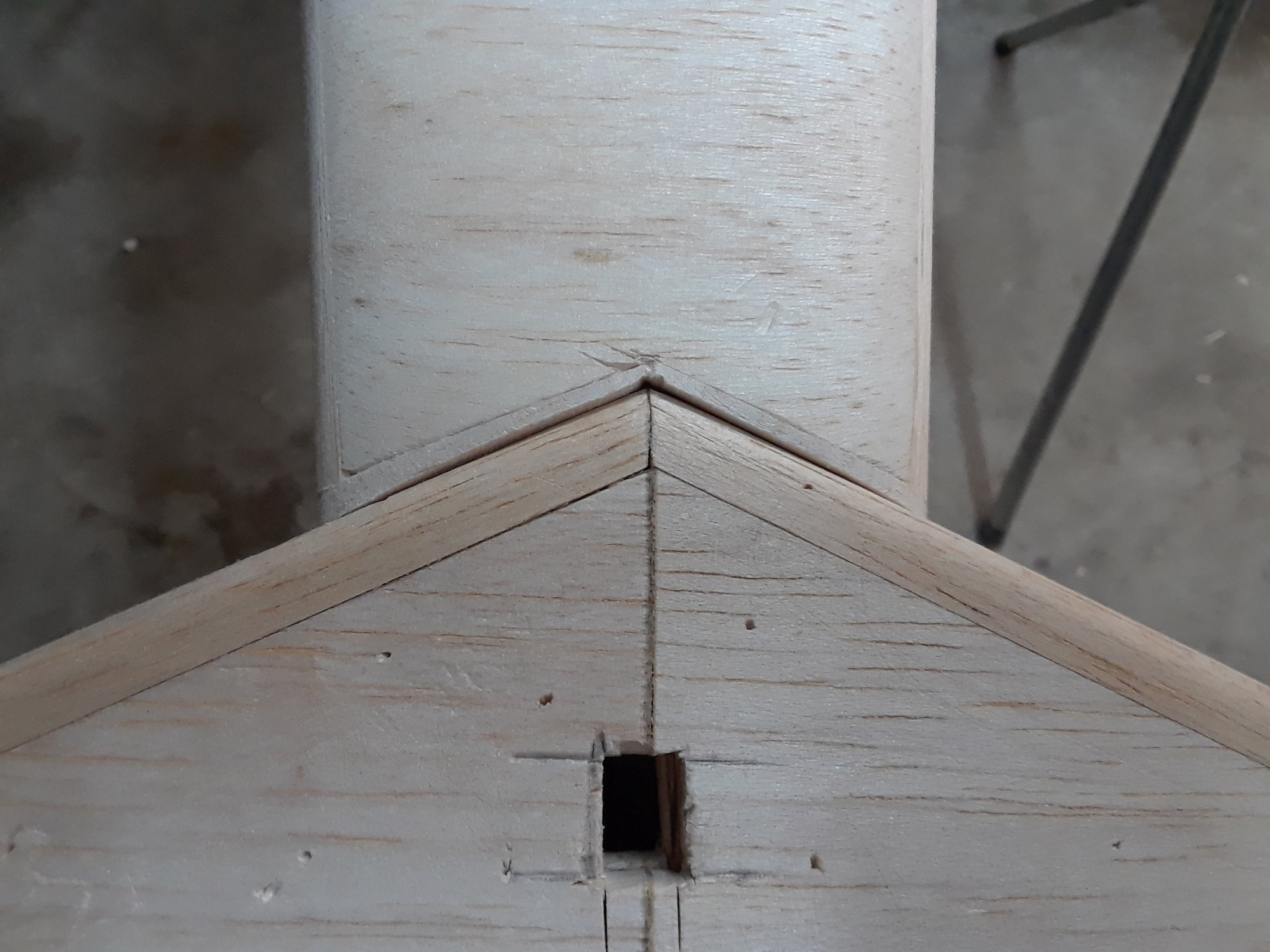
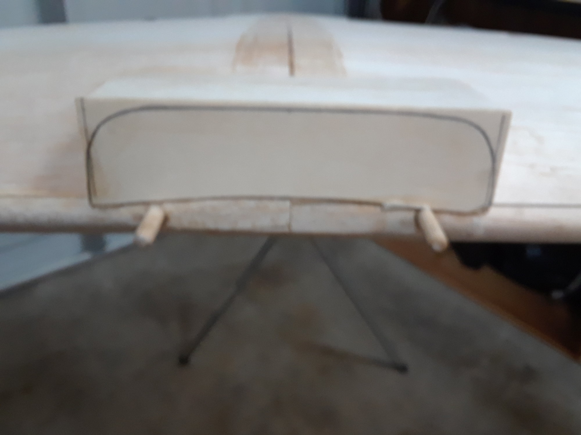
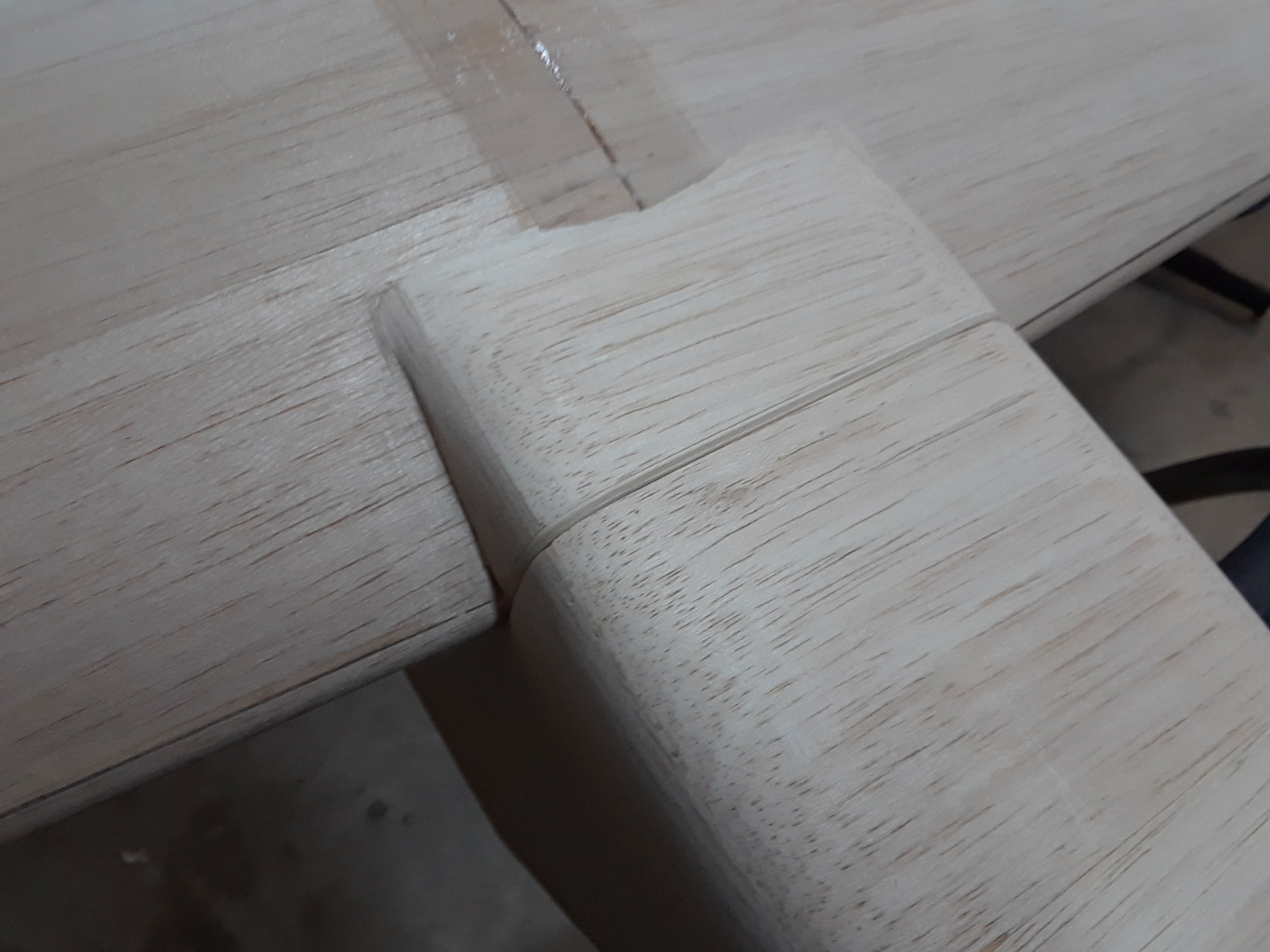
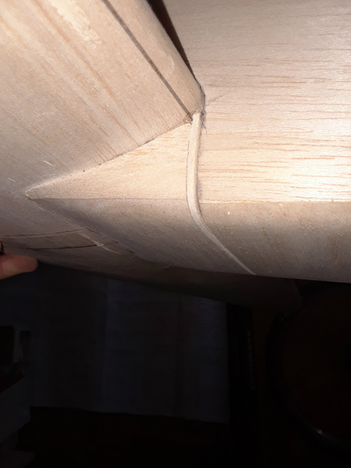
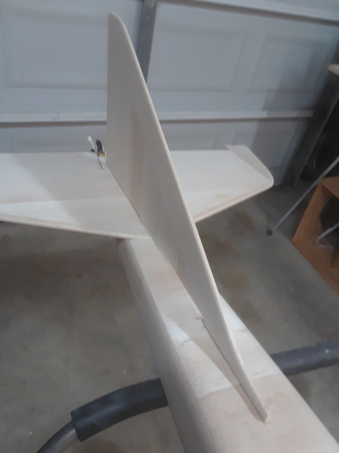
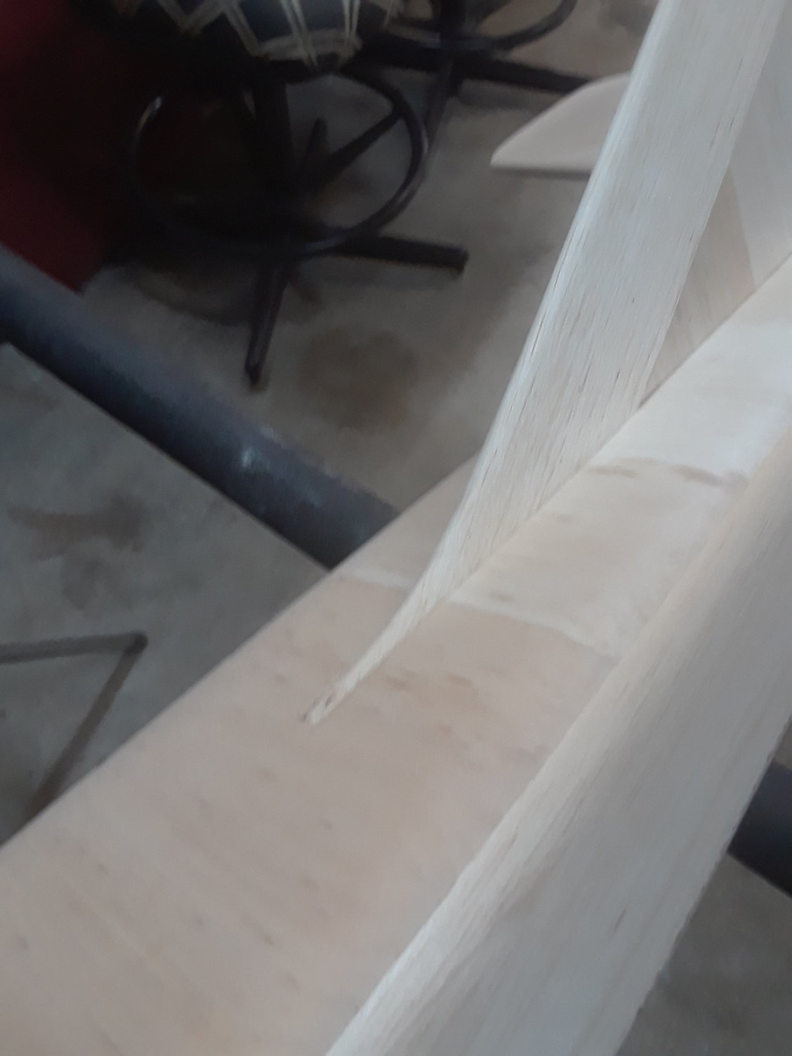
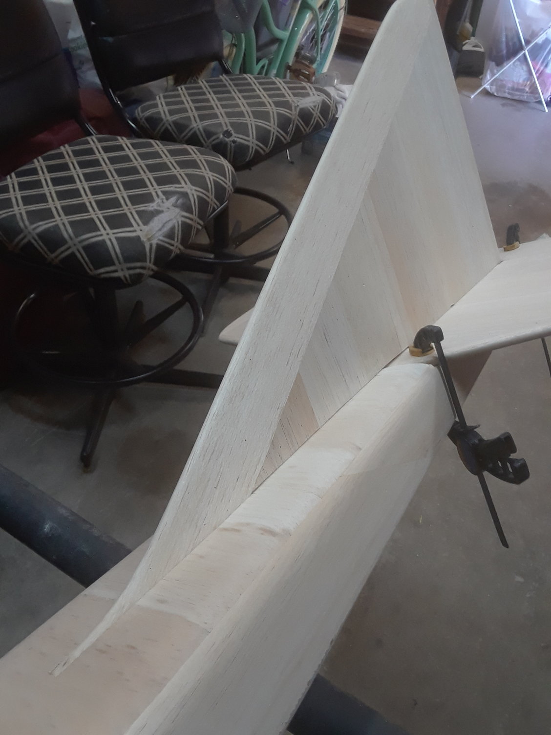
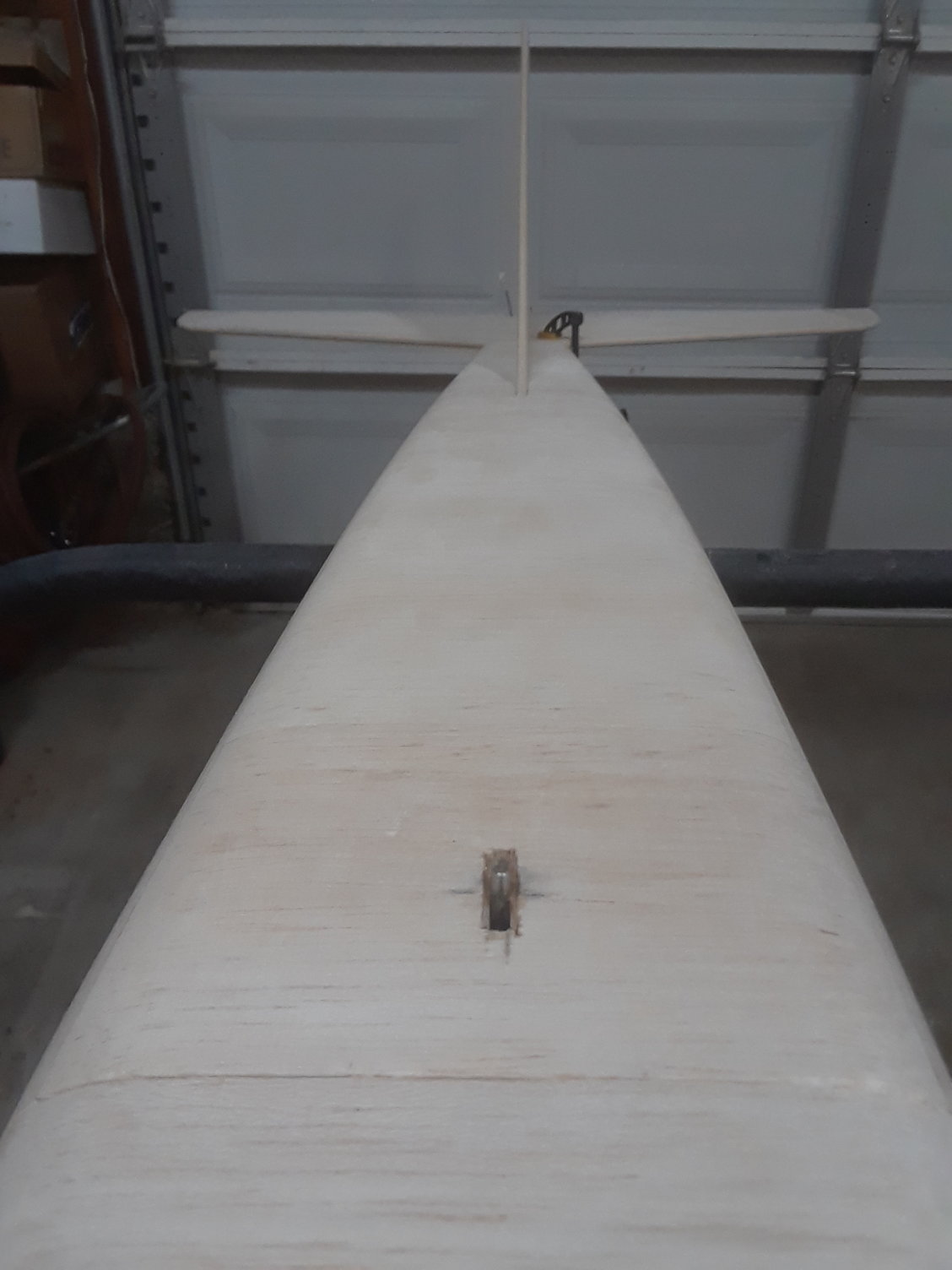
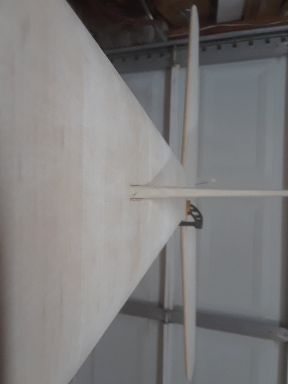
Wing fairing is done, also fixing a few little gaps here and there ( cosmetic details )
When I get the retracts set ( soon ) I will build the wheel well, so far that is the only thing to build on the jet.
I'm glad it is build, my free time has gone South, I got 9 days work weeks ahead of me for the next 6 months

Last edited by CARS II; 06-20-2018 at 03:42 PM.
06-25-2018, 08:14 AM
#4079

My Feedback: (3)
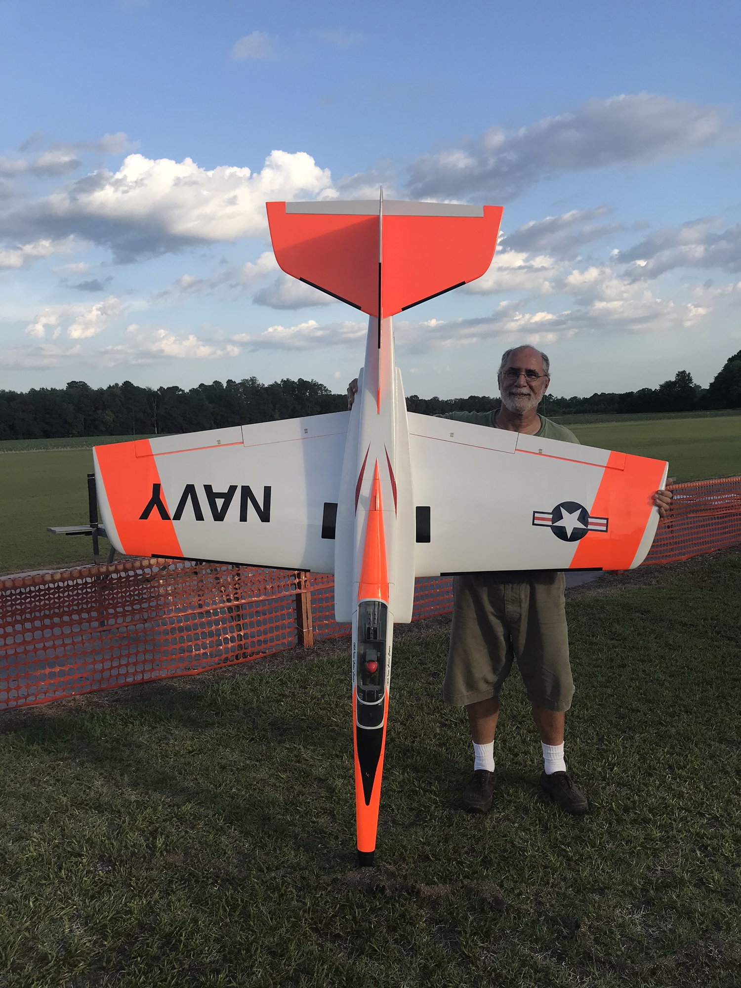
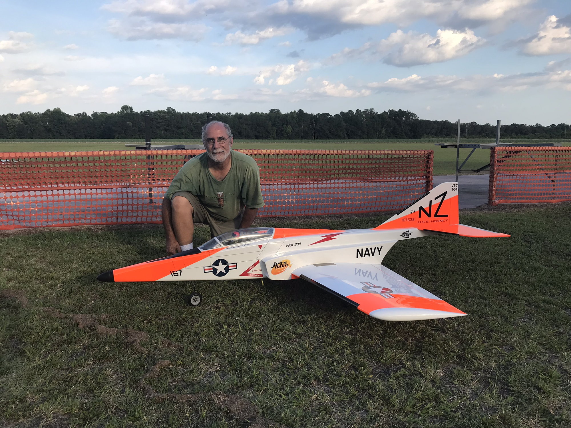
Awesome job by N99JH building his R54. Josh is an excellent builder with meticulous detail. This is a good trait for building and flying rc jets! This R54 will be a great platform for his training and journey towards turbine waiver.
The CG was bang on right off the table thanks to all the great input on this forum and use of the Xicoy CG machine. He is using a Jetsmunt M100XBL and so he extended the nose to help with CG and to change the aesthetics more to his liking. I think it came out very nice!
Pictures below after one of the first 5 flights that we now have on it. It’s now fully trimmed out and ready to begin turbine training with Josh. The high viz scheme shows up very well in the sky!
Very nice kit and resulting jet by BTE! I look forward to more flights on it as training progresses.
Last edited by jsnipes; 06-25-2018 at 08:19 AM.
06-25-2018, 02:07 PM
#4081


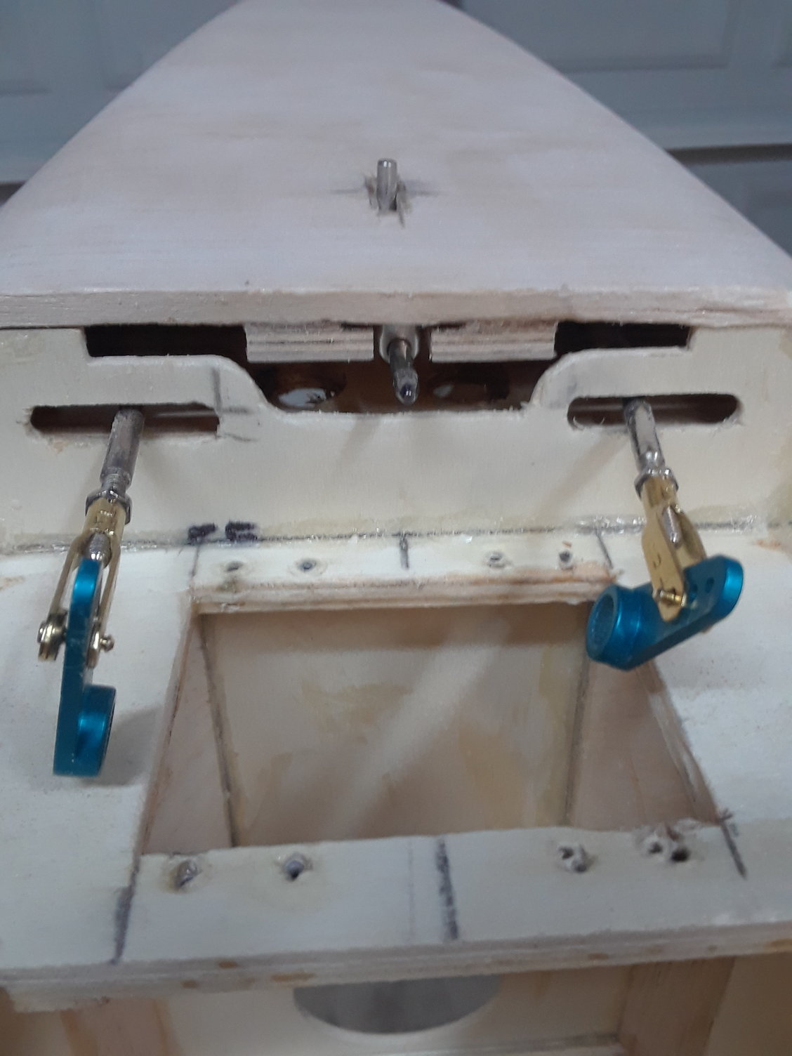
I'd recommend against this set up. Those aluminum arms are great. The clevis's are great, but not together. Metal on metal connections are a no no. It used to be due to RF interference which I don't think is as big an issue with 2.4 but the aluminum arms have threaded holes (or at least all I've seen do). The aluminum arms are really meant for ball link clevis's that are attached with a bolt and nut. The snap link clevis's should really have a nylon bushing to ensure a slop free fit.
I would either go to heavy duty nylon servo arms (not the dubro ones) or preferably go to a ball link instead of the snap link.
I would either go to heavy duty nylon servo arms (not the dubro ones) or preferably go to a ball link instead of the snap link.
 06-25-2018, 02:39 PM
#4082

My Feedback: (66)
I do not see any problem with this set up. I have seen them at work on numerous giant scale models and large jets, and, never heard or seen slop developing. The forces are simply not strong enough to create an elongated hole over the life span of a model airplane. I am far more concerned about the rolled threads on typical 4-40 push rods breaking due to stress risers at the transition are from round rod to threaded section.
Just my 2C of course.
Just my 2C of course.
06-25-2018, 03:21 PM
#4083

Congrats!!!. That is the best looking Reaction 54 I have ever seen.
I have used metal clevises on Hitec metal servo arms on every jet I have had and I just switched to 2.4 a couple of years ago.. Never had an issue. I'm flying a Facet that I built in 2004 that has hundreds of flights.
I have used metal clevises on Hitec metal servo arms on every jet I have had and I just switched to 2.4 a couple of years ago.. Never had an issue. I'm flying a Facet that I built in 2004 that has hundreds of flights.
06-25-2018, 03:37 PM
#4084

If memory serves, only the outermost hole of these Hitec servo arms is threaded. The rest are sized for a good fit with a clevis pin. I'm not crazy about metal on metal either, but that's just an ingrained memory that goes back to early radio days. Even then, it took vibration to cause an RF problem, so not an issue with turbines and modern radios.
06-25-2018, 03:50 PM
#4085
My Feedback: (66)
Congrats!!!. That is the best looking Reaction 54 I have ever seen.
I have used metal clevises on Hitec metal servo arms on every jet I have had and I just switched to 2.4 a couple of years ago.. Never had an issue. I'm flying a Facet that I built in 2004 that has hundreds of flights.
I have used metal clevises on Hitec metal servo arms on every jet I have had and I just switched to 2.4 a couple of years ago.. Never had an issue. I'm flying a Facet that I built in 2004 that has hundreds of flights.
06-25-2018, 07:13 PM
#4086
I do not see any problem with this set up. I have seen them at work on numerous giant scale models and large jets, and, never heard or seen slop developing. The forces are simply not strong enough to create an elongated hole over the life span of a model airplane. I am far more concerned about the rolled threads on typical 4-40 push rods breaking due to stress risers at the transition are from round rod to threaded section.
Just my 2C of course.
Just my 2C of course.
First one was the metal pin in the clevis broke from the fixed side. This was not an offshore pin but a dubro clevis. Now whether it was faulty or not I don't know, but it was in an aluminum servo arm.
Second one was on a plane with a large throw and it also broke the pin in the clevis however that one had actually caused the aluminum in the horn to gall and it seized the pin into the arm. The pin broke free in the clevis and allowed it to rotate. Admittedly these were both in 4 stroke powered pattern airplanes where there was more vibration and that may have added to it but every other pattern airplane I had was heavy duty nylon servo arms and never ever had an issue.
Since that time I have NEVER put steel clevis's into aluminum arms.
06-25-2018, 11:55 PM
#4087
I'm listening, new HS 5645 servos have a HD arm that I have used on my Boomerang before, I most likely will be using them on this jet, since you mention your experience with the HD Dubro before I checked the arms on the Boomer and I'm using the HD HS ones not the Dubro as I thought.
Thank you for the suggestion Jeremy, always welcome.
Thank you for the suggestion Jeremy, always welcome.
Last edited by CARS II; 06-26-2018 at 12:00 AM.
 06-27-2018, 10:53 AM
#4090

You're going to think I'm full of it I'm sure, but my 2 experiences with the steel quick links into aluminum horns ended as follows.
First one was the metal pin in the clevis broke from the fixed side. This was not an offshore pin but a dubro clevis. Now whether it was faulty or not I don't know, but it was in an aluminum servo arm.
Second one was on a plane with a large throw and it also broke the pin in the clevis however that one had actually caused the aluminum in the horn to gall and it seized the pin into the arm. The pin broke free in the clevis and allowed it to rotate. Admittedly these were both in 4 stroke powered pattern airplanes where there was more vibration and that may have added to it but every other pattern airplane I had was heavy duty nylon servo arms and never ever had an issue.
Since that time I have NEVER put steel clevis's into aluminum arms.
Larry
 07-02-2018, 07:16 PM
#4093
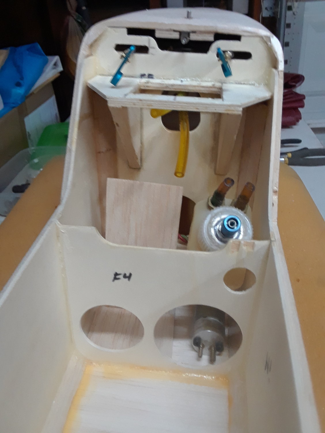
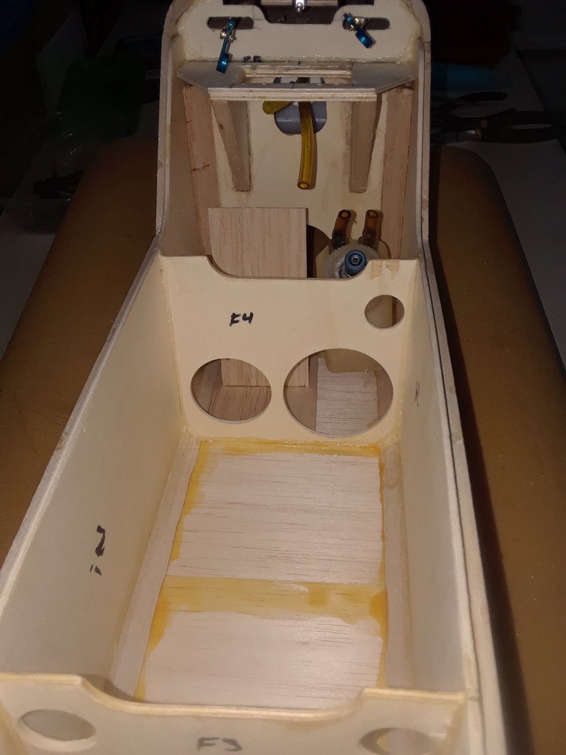
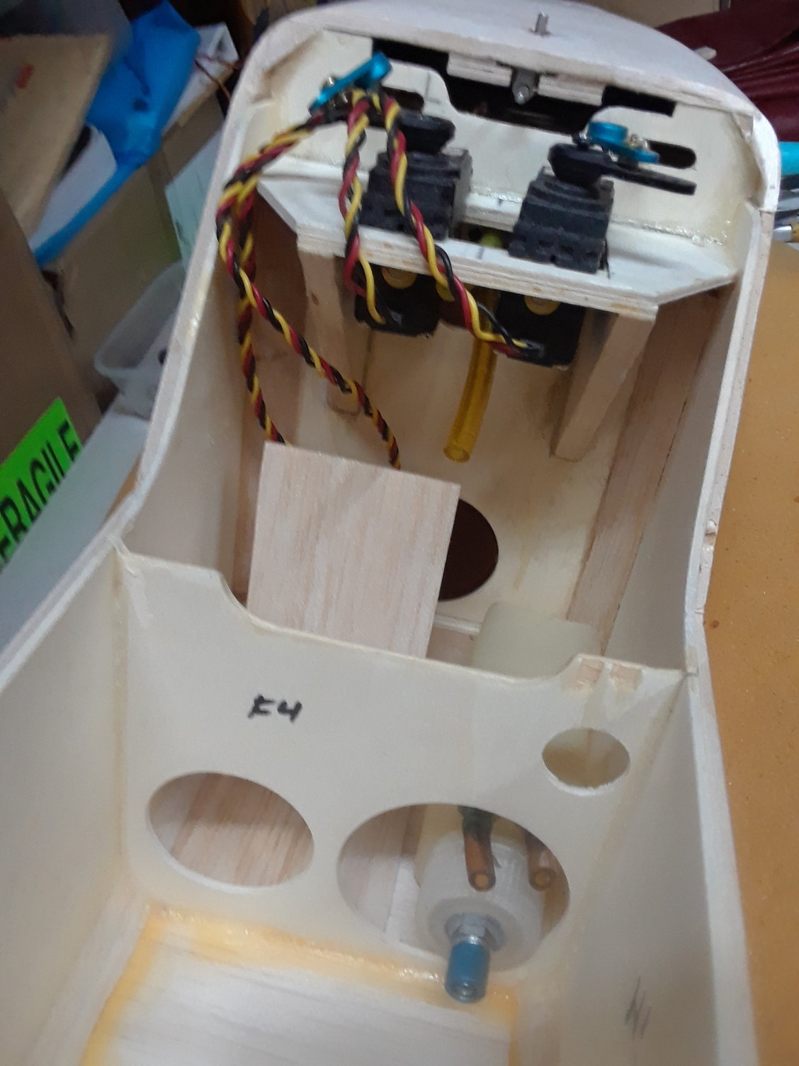
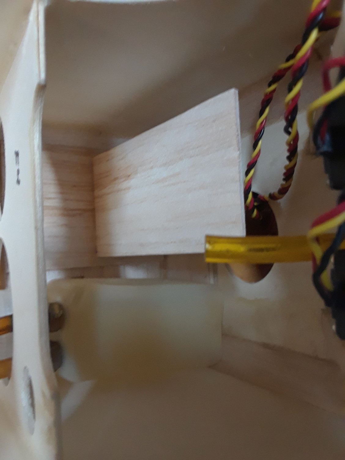
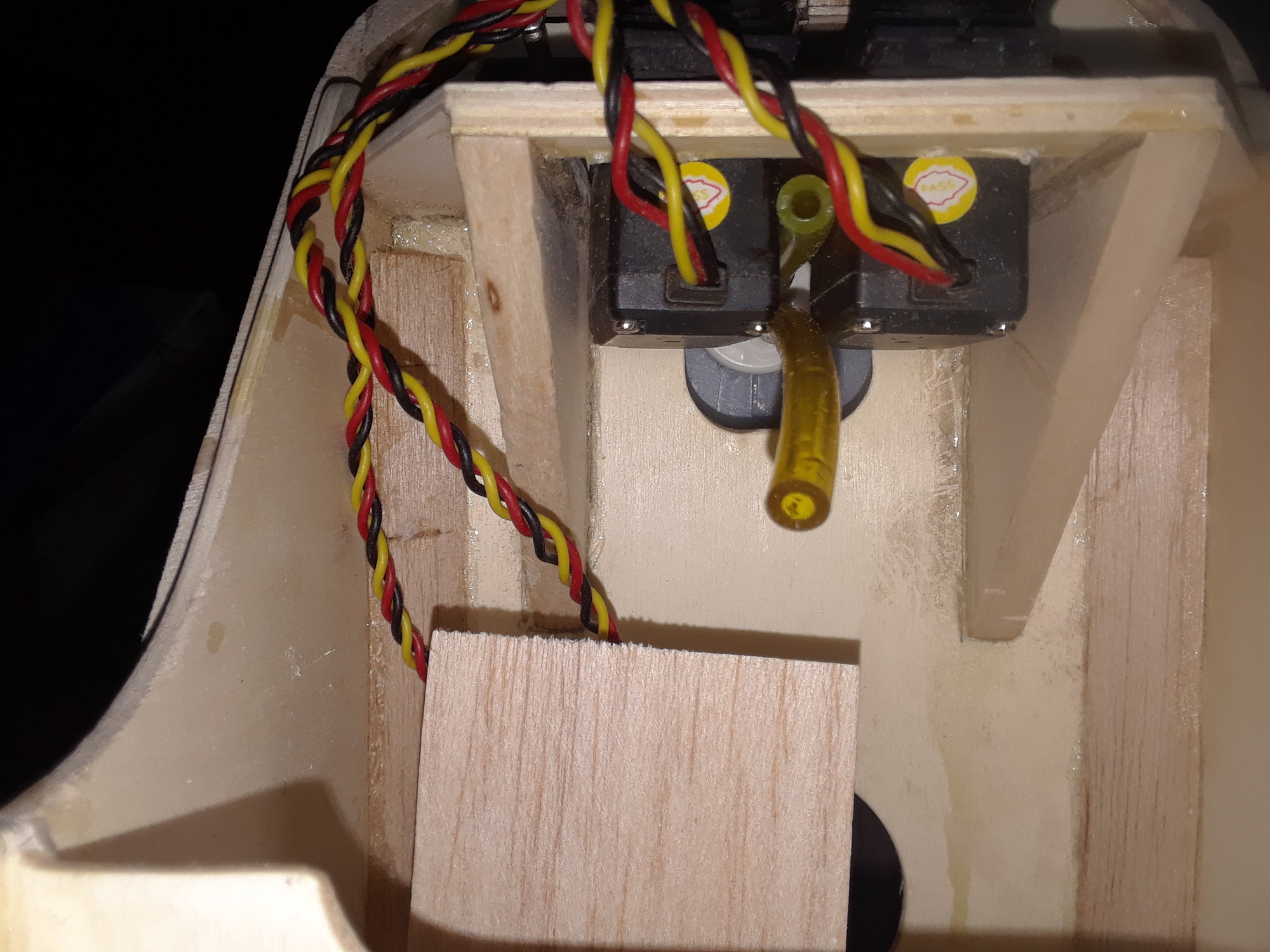
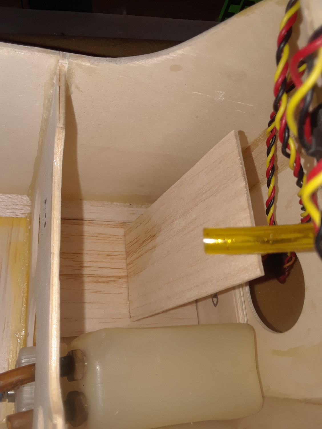
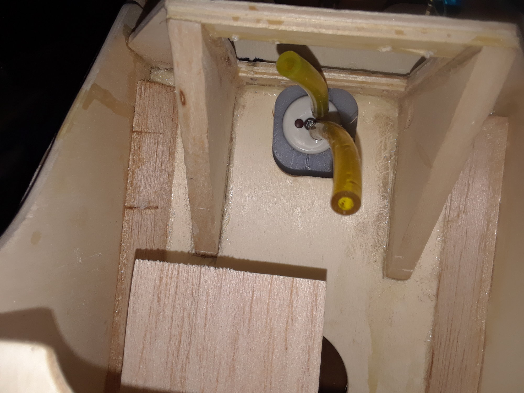
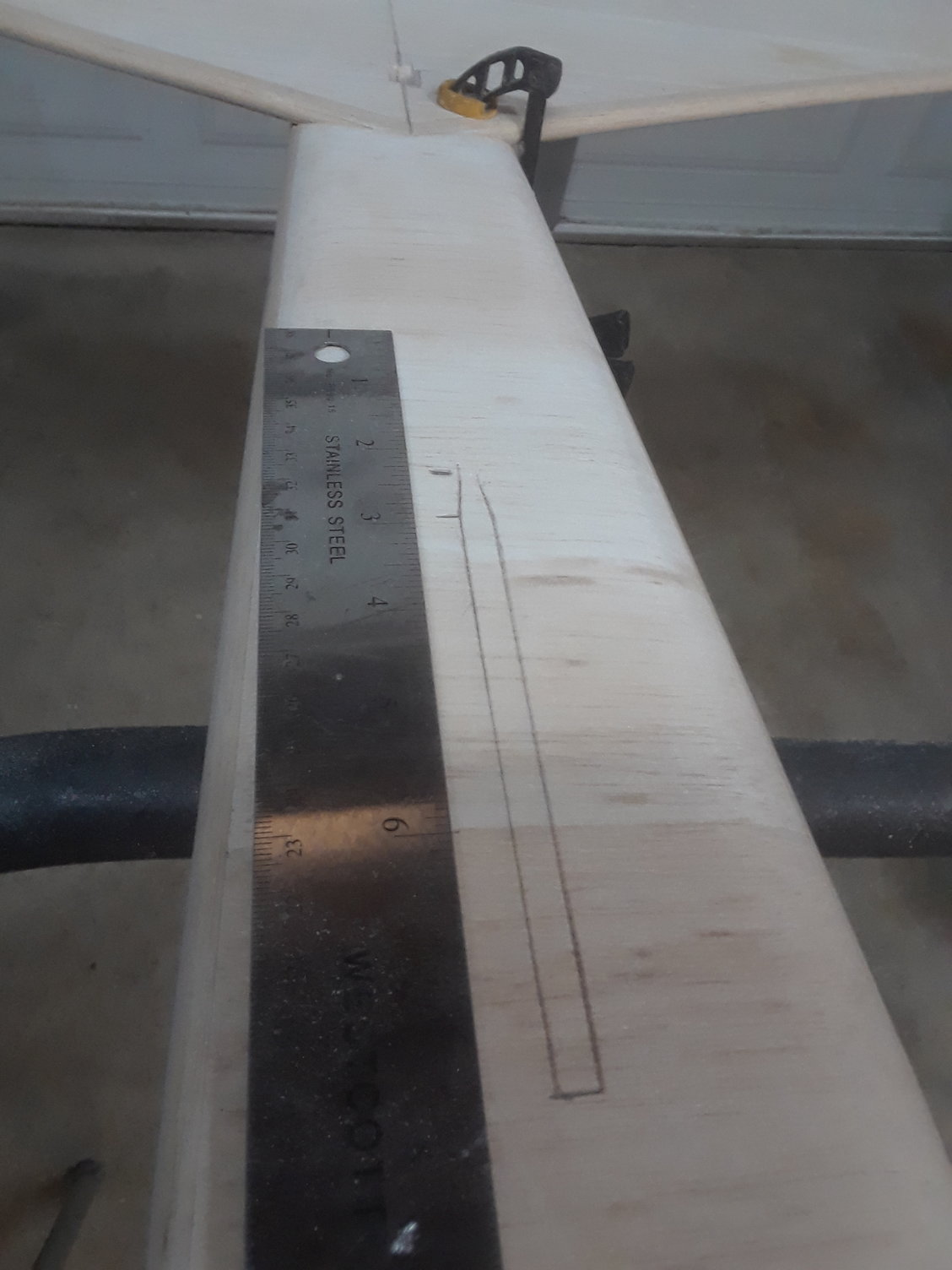
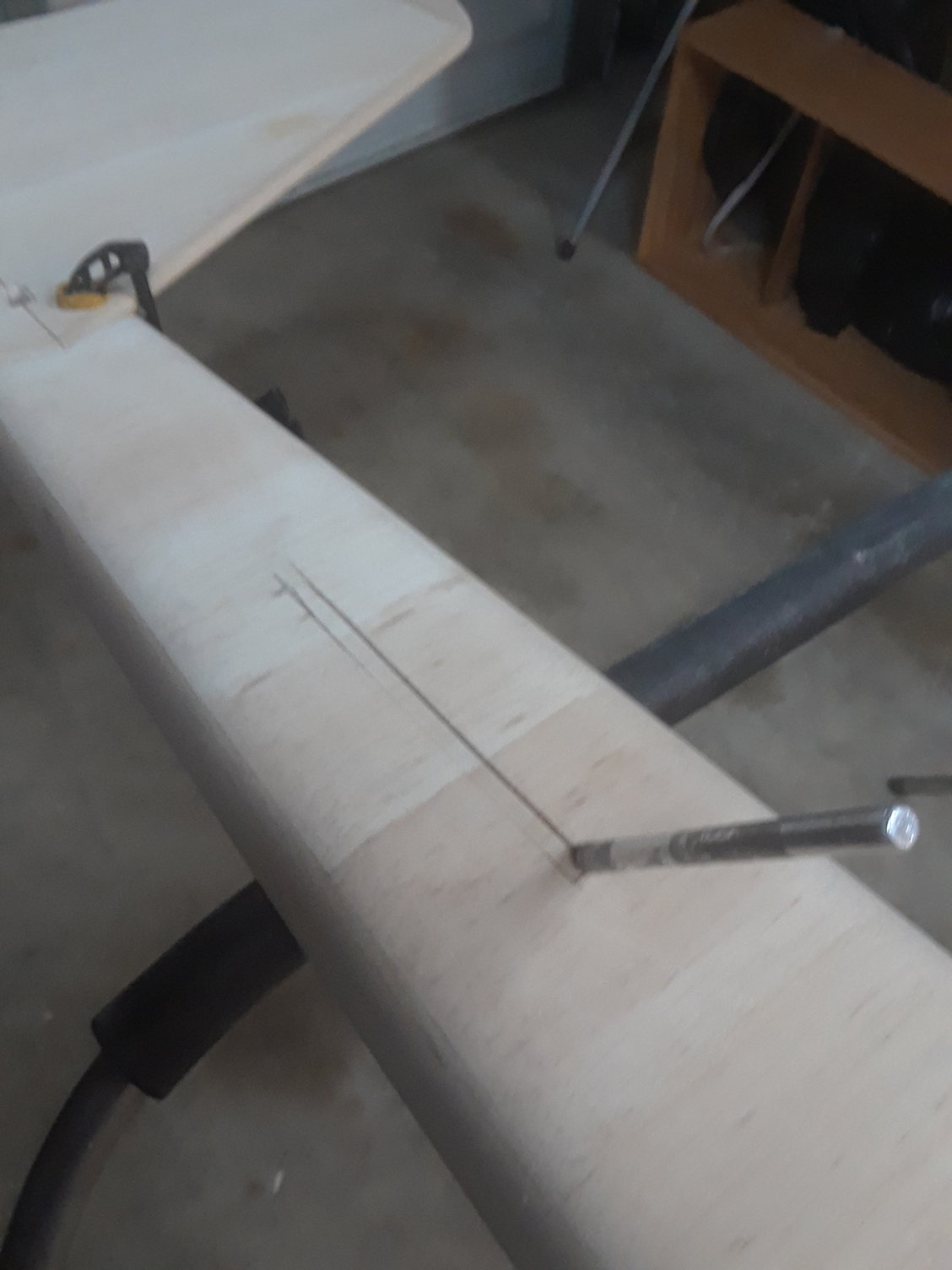
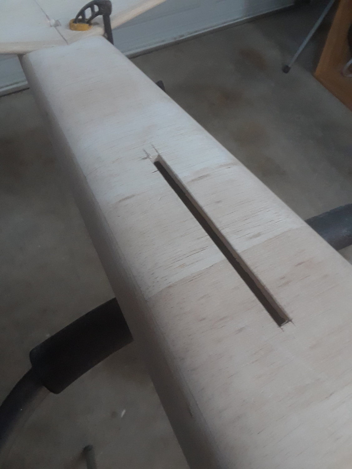
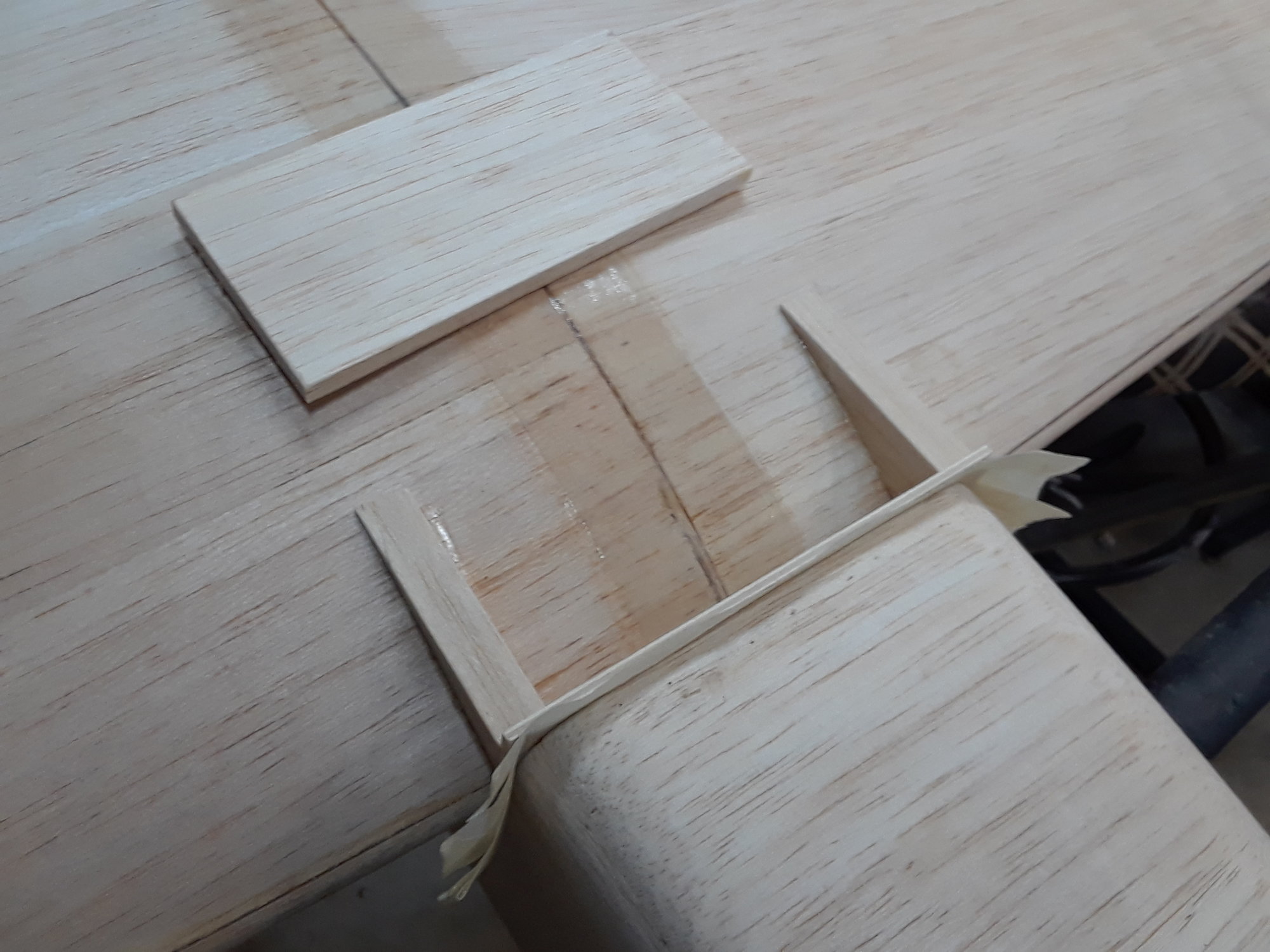
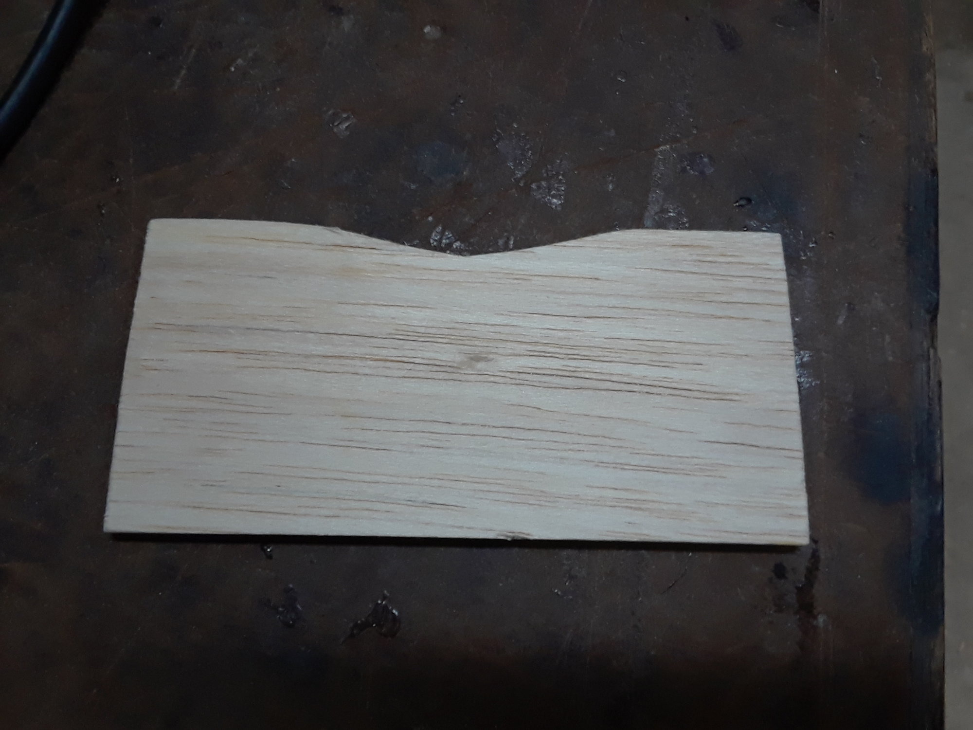
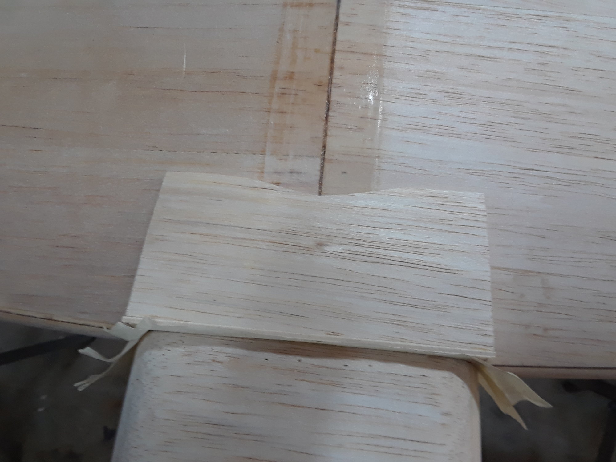
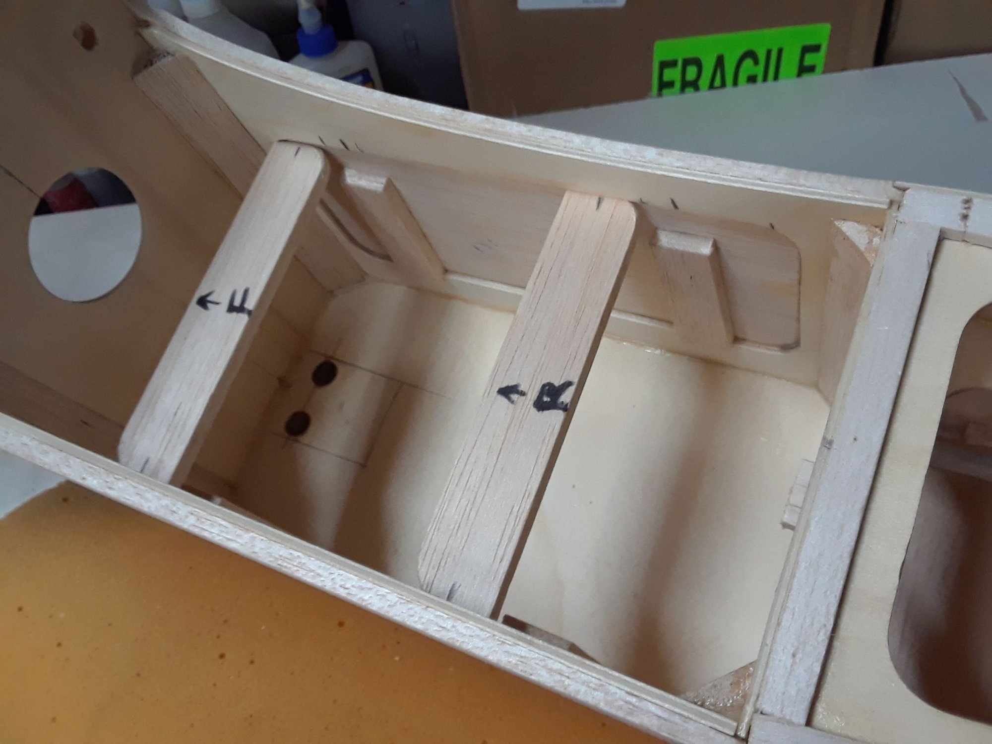
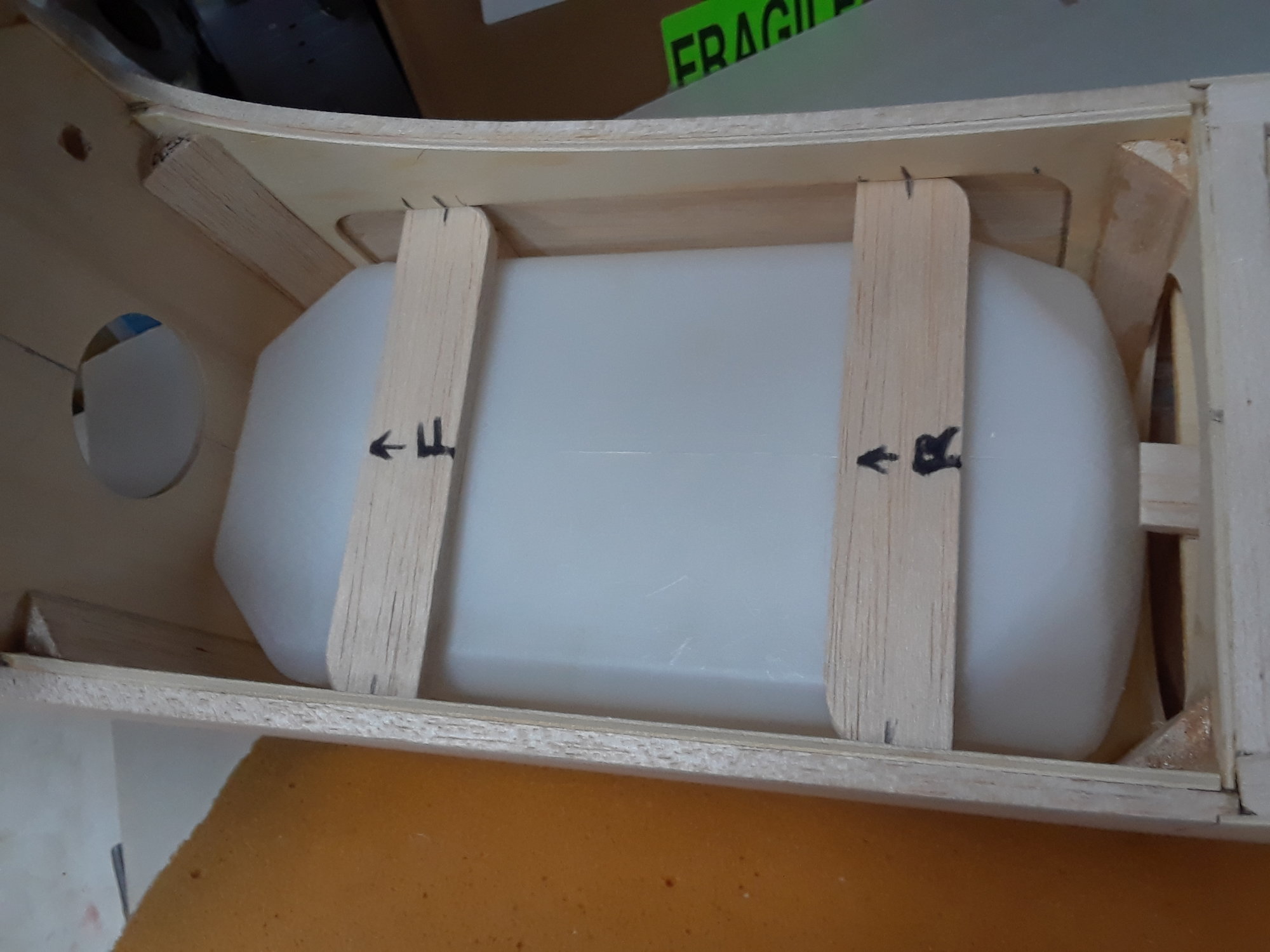
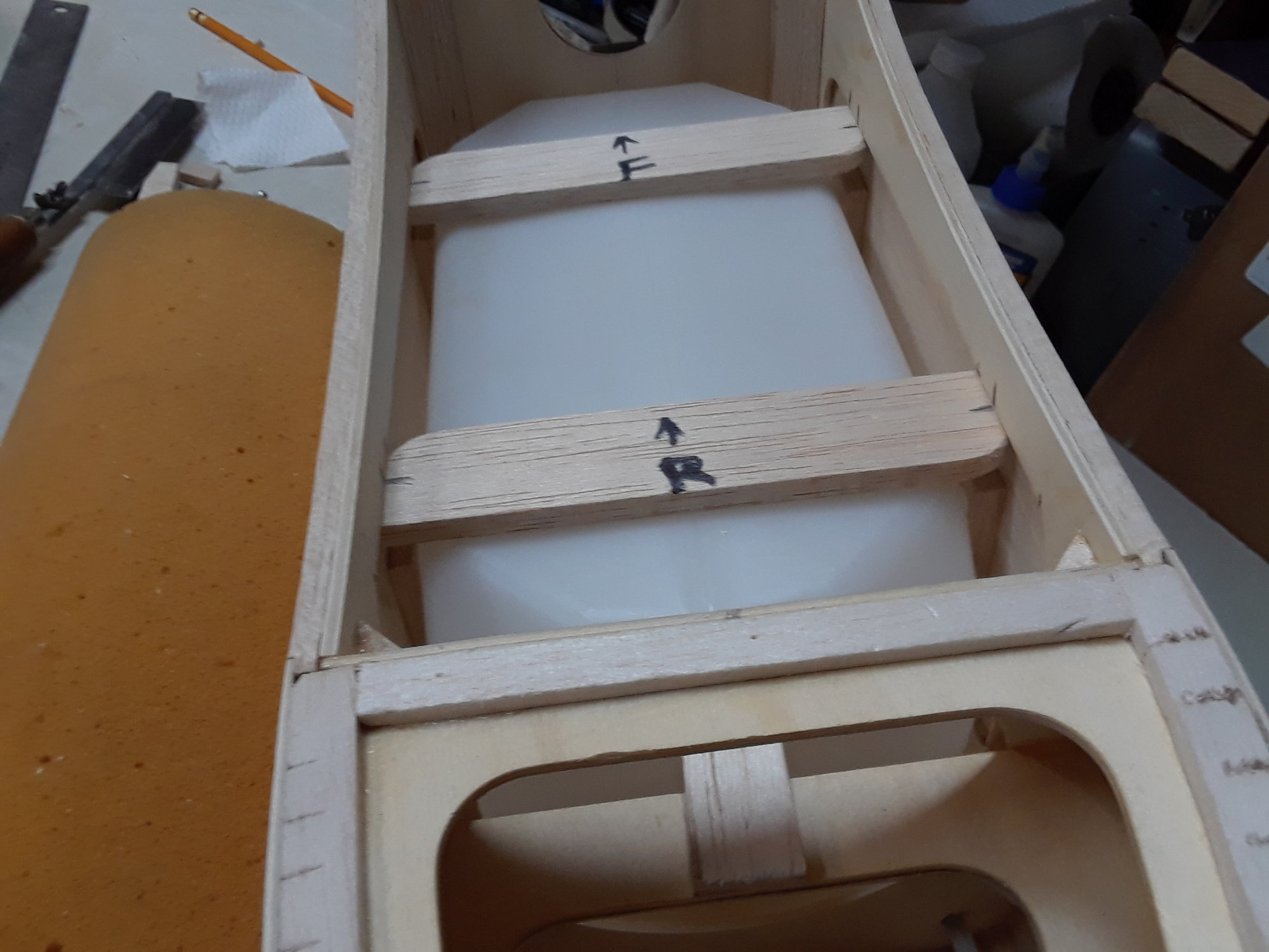
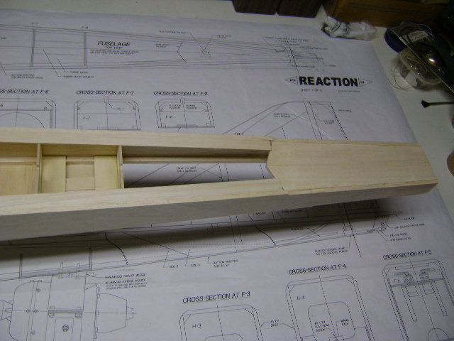
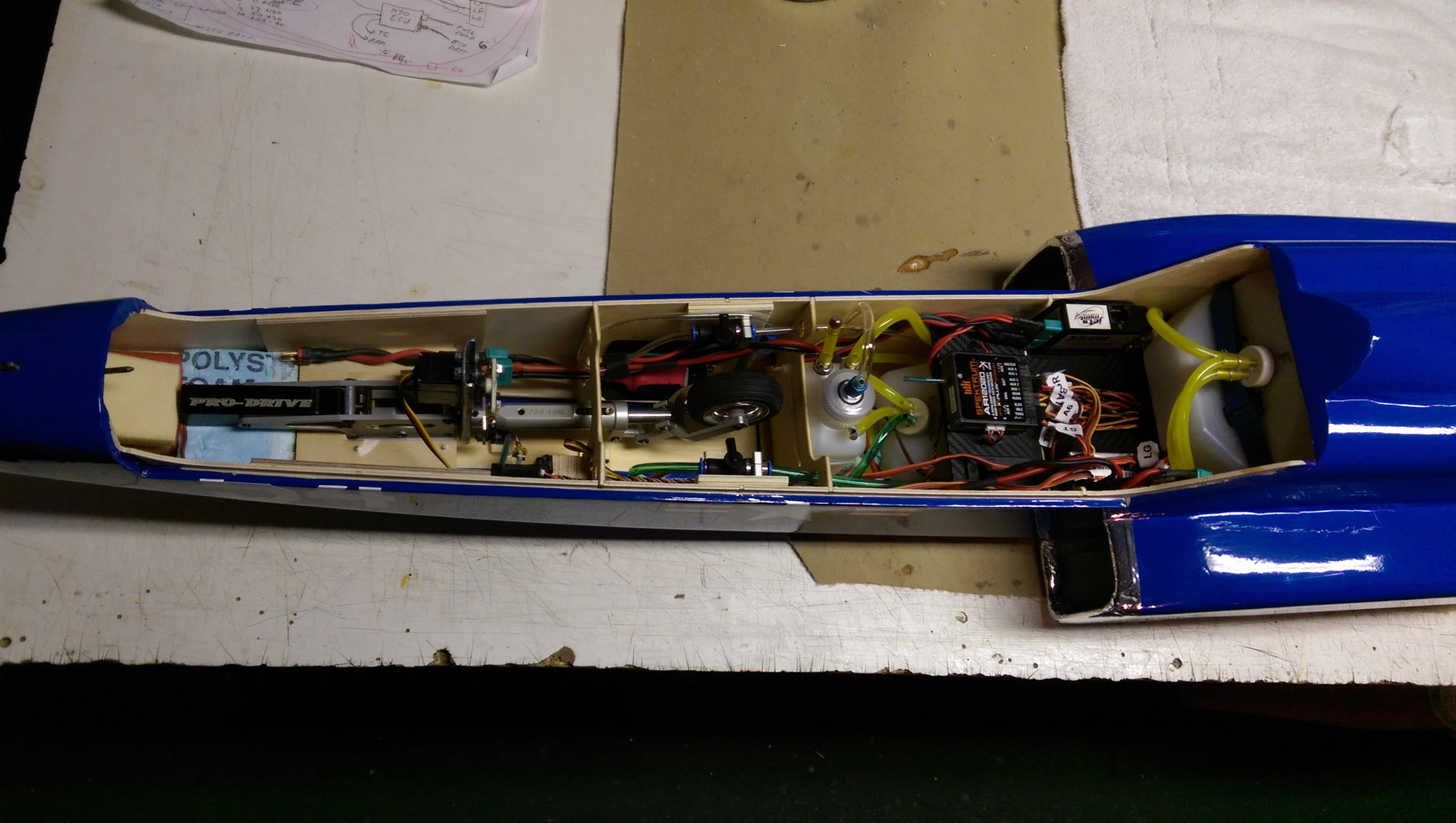
Working on the fuel system, this to confirms my ideas, I will be getting me some Nelgene bottles to complete it, the balsa mock up is for the 16 oz bottle, it looks like I will be able to install the 16 oz bottle and the 4 oz bottle ( UAT ) in the same compartment, I will add a ply floor to enhance the strength of that section because of the extra weight from the fuel, the pump will go right on front of the UAT or under.
Last edited by CARS II; 07-02-2018 at 07:59 PM. Reason: 6
07-03-2018, 02:03 AM
#4095
My Feedback: (66)
Working on the fuel system, this to confirms my ideas, I will be getting me some Nelgene bottles to complete it, the balsa mock up is for the 16 oz bottle, it looks like I will be able to install the 16 oz bottle and the 4 oz bottle ( UAT ) in the same compartment, I will add a ply floor to enhance the strength of that section because of the extra weight from the fuel, the pump will go right on front of the UAT or under.
Joshua
07-03-2018, 10:40 AM
#4097
My Feedback: (3)
My $0.02 .... With a 100N turbine I would not want anything smaller than the 80 oz. We takeoff, fly 5.5 minutes then land with enough fuel for a couple go rounds if needed. If you�re going to run a smaller turbine you may or may not want to consider something else ... you�ll be running at a higher power setting with a smaller turbine so its hard to say which would have more/less actual fuel consumption with mixed throttle use. It seems to fit well and is close, maybe a little forward to target CG location so as you fly it will be coming back toward target CG. Josh�s rotates on takeoff very well and flair�s for landing very well at our current CG position. Takeoff, fly, and land with same control throws.
Hope this helps.
JS
Hope this helps.
JS
07-03-2018, 10:51 AM
#4098
My Feedback: (48)
An 80 oz. Dubro tank fits if you move the elevator and rudder servos to the rear. I made the back of the fuse 1 inch wider to accommodate the servos. this has the added advantage of eliminating those long cables. I also had room for a 24 oz. smoke tank under the receiver.
.
.
07-03-2018, 11:28 AM
#4100
My Feedback: (5)
Join Date: Dec 2011
Location: Holland Patent,
NY
Posts: 717
Likes: 0
Received 0 Likes
on
0 Posts
Carlos,
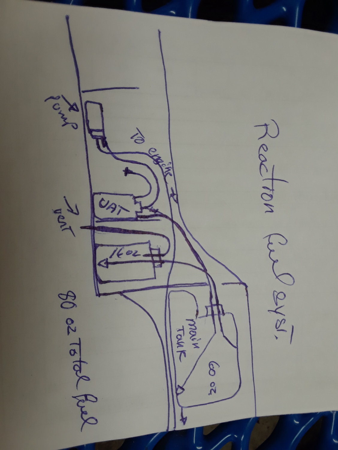
On your Post #4091 showing your planned 80 oz fuel system layout, you should vent the main 60 oz tank, not the 16 oz auxiliary tank. Venting the aux tank will drain the main tank due to gravity flow as the main is higher in the fuselage. Personally I favor JoeFlyer's concept (Post 4098) of widening the fuselage rear and installing the rudder and elevator servos to the back. I will follow his concept in my own 85% scale reduction of a Reaction 54. This reduced scale Reaction 54 will employ a single 60 oz Dubro tank to feed a Wren 44K turbine. You may be too far along to widen the fuselage rear but be sure to vent the main 60 oz tank not the 16 oz aux tank.
Regards,
Art

